Roombanker User Manual
Revision History
| Rev. | Date | Update Description |
|---|---|---|
| 1.3.2 | 2026-07-30 | New function: 1.Supports linkage of indoor IPCs and outdoor IPCs with the hub. |
| 1.3.1 | 2026-06-30 | New function: 1.Added Wireless Transmitter. 2.There's an exciting addition to our app's home page - the Device Search feature! 3.Hub defends against AirSnitch attacks. 4.Add silent emergency alarm function to the custom buttons of the keyfob. 5.Support Russian. Optimization: 1.Optimize the arming operation when an alarm occurs. 2.Optimize the display of camera messages. |
| 1.3.0 | 2026-03-31 | New function: 1.Expanded Language Support: Added support for Bahasa Melayu,Bahasa Indonesia,Tiếng Việt,ภาษาไทย,Filipino,Latina,Bosanski. 2. Introduced a new gateway panel configuration option in System Settings (collapsed by default). 3.Added configuration options for tamper switches on both Indoor Siren and Outdoor Siren. 4.Door Magnetic Sensor has been renamed to Door Window Sensor for better clarity. 5.The username is now saved after logout for easier subsequent logins. Optimization: 1.Optimized Hub message filtering; all hub messages are now displayed by default. 2.Optimized Hub upgrade and startup speed. 3.Enhanced display layout for Arabic language pages. |
| 1.2.2 | 2026-01-26 | New function: 1.Add historical data saving functionality to the Temperature & Humidity Monitor. 2.Supports multiple custom arming modes to be armed simultaneously. 3.Local account now allows room configuration for remote controls. 4.Added alerts for abnormal devices during the arming process. 5.Added support Arabic . Optimization: 1.Improve the accuracy of QR code scanning in the app. 2.Optimize the room interface display. |
| 1.2.1 | 2025-09-25 | New function: 1.Added Outdoor PIR Sensor. 2.Wall Switch support pulse mode. 3.ARC has added Periodic Report Test. 4.Indoor IPC supports audio alarms, including noise detection and unusual sound patrol. 5.Indoor IPC has added a scheduled patrol function. Optimization: Optimize message push logic. 2.Optimize the user interface for Greek. |
| 1.2.0 | 2025-07-23 | New function: 1.Added Outdoor Camera and Indoor Camera. 2.Added Support Romanian, Macedonian, Croatian, Greek and Dutch. 3.It supports the super administrator to transfer their own user permissions to other users. 4.Add settings for important alarm message reminders. Optimization: 1.Custom arming/scene allows users to upload local photos by themselves. 2.Optimize the arming and disarming prompt information. 3.Optimized user experience. |
| 1.1.3 | 2024-03-06 | Optimization: 1. Added outdoor siren status light config. 2. Added PIR Sensor sensitivity config. 3. Optimized user experience. |
| 1.1.2 | 2025-01-20 | New function: 1. Independent sensor delay config for away - defense. 2.LTE external antenna switch. 3.APP emergency alarm. 4.Peripheral device firmware update. Optimization: Bug fixed. |
| 1.1.1 | 2024-09-27 | New function: 1. Added Turkish language. Optimization: Bug fixed. |
| 1.1.0 | 2024-08-13 | New function: 1. Added DC 09 protocol alarm reporting. 2. Added relay pulse control mode. 3. Added Wi-Fi network modification capability. 4. Added hub IP address display. 5. Added "Hardware Version" to the device's basic information page. 6. Added hub fault status and fault list viewing. 7. Added status light for outdoor siren operation. 8. Added RBF smoke detector. 9. Added keypad unlock feature. 10. Added video guide for batch adding peripherals. Optimization: 1. Optimized issue where peripherals appeared online after going offline. 2. Optimized peripheral alarm icons to differentiate between tamper, intrusion, water leak, emergency, smoke, fire, and medical alarms. |
| 1.0.2 | 2024-05-14 | New function: 1. Daylight Saving Time function 2. SIM Card PIN Code unlock function 3. Temperature and humidity sensor Fahrenheit and Celsius switching function 4. German language supported Optimization: 1. PIR Sensor, Siren function optimized 2. Bug fixed |
| 1.0.1 | 2024-03-18 | 1. Bug fixed |
| 1.0 | 2024-01-24 | 1. New version release |
Overview
Purpose of the Manual
The main purpose of the manual contains 3 parts:
● To introduce the features and specifications of Roombanker Security Product System
● To introduce how to register, configure and operate the devices from RB Link APP
● To introduce the installation and function test method of the whole system
Scope of the Manual
All the functions described in the manual are based on the products and version showing in the form below. You may find some functions cannot be achieved if your devices are not the latest version, please check your devices version and update to the latest from APP if so.
Device name and latest available version
| Device | Version | Spec | QSG | Device | Version | Spec | QSG |
|---|---|---|---|---|---|---|---|
| Home Security Hub (R2) | v1.0.0 | View | View | PIR Sensor | v1.0.0 | View | View |
| Home Security Hub (R2 PRO) | v1.0.0 | View | View | Panic Button | v1.0.0 | View | View |
| Keypad | v1.0.0 | View | View | Door Window Sensor | v1.0.0 | View | View |
| Relay | v1.0.0 | View | View | Water Leak Detector | v1.0.0 | View | View |
| Wall Switch | v1.0.0 | View | View | Temperature Humidity Monitor | v1.0.0 | View | View |
| Indoor Siren | v1.0.0 | View | View | Smoke Detector | v1.0.0 | View | View |
| Outdoor Siren | v1.0.0 | View | View | RB Link (App) | v1.0.0 | / | / |
| Keyfob | v0.0.8 | View | View | Indoor IPC | v1.0.0 | View | View |
| Smart Plug (US) | v1.0.0 | View | View | Outdoor IPC | v1.0.0 | View | View |
| Smart Plug (EU) | v1.0.0 | View | View | Outdoor PIR Sensor(IR+MW) | v1.0.0 | View | View |
| Smart Plug (UK) | v1.0.0 | View | View | Door Window Sensor(Anti-masking) | v1.0.0 | View | View |
| Transmitter | v1.0.0 | View | View | Repeater | v1.0.0 | View | View |
Symbol Conventions
| Symbol | Description |
|---|---|
 Danger Danger | Indicates a hazardous situation which, if not avoided, will or could result in death or serious injury. |
 Caution Caution | Indicates a hazardous situation which, if not avoided, will or could result in equipment damage or performance degradation. |
 Note Note | Provides additional information to emphasize or supplement important points of the main text. |
Charter 1. System Introduction
1.1 Overview of the System
● Product Positioning:
Roombanker focus on the smart security solutions centered around wireless intrusion alarm system, and extended business to a multitude of applications such as Energy Management, Environmental Safety, Home Automation. All of these applications can be conveniently managed via a one-stop mobile app.
● Application Scenario:
Roombanker offers security solutions to Residential and SMB users, such as Apartment, House & Villa, Small Shop, Office Building, Motel, and more.
● System Topology:
It has four parts to consist of the whole system, which are Peripherals, Hub, Roombanker Cloud, RB Link APP.
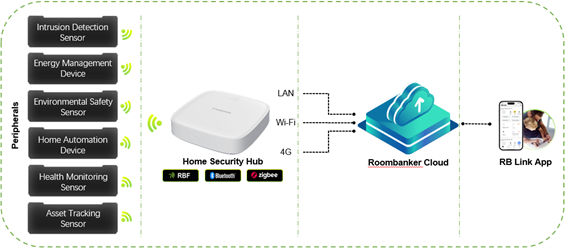
● Working Principle:
The Home Security Hub is the brain of the whole system, it communicates with peripherals via RBF / Zigbee wireless protocol.
Once an alarm occurred, Hub reports the alarm to cloud via LAN / Wi-Fi / 4G, activates the sirens within 0.5 seconds, and notifies the users via APP. Meanwhile, if the users operate the system, such as disarm, Hub will turn siren off and disarm all sensors.
RBF is a self-developed encrypted wireless protocol by Roombanker, aim to enhance the communication between devices, the transmission range is up to 3,500m in open area. It contains advanced technologies design, such as TDMA, Frequency Hopping, Power Adjustment, Multi-Band Transmission with Low Power, to guarantee a stable, secure, highly efficient wireless communication.
1.2 System Key Features
● Ultra-long range, reliable transmission
● Reliable alarm protection, day and night
● Multi-mode arming/disarming
● Instant alarm and real-time notification
● Manage smart devices with just one APP
● Esay installation & Easy DIY
1.3 Spec of Hub
Home security Hub has two different models, called R2 PRO and R2, below form describes the brief comparison between two models.
| Specifications | Home Hub (R2) | Home Hub (R2 PRO) |
|---|---|---|
| Transmission Technology | RBF | RBF |
| Transmission Method | Two-way wireless (RBF) | |
| Transmission Frequency | 868/915MHz (RBF) | |
| Transmission Security | AES128 Encryption (RBF) | |
| Peripherals Connected | Up to 64 | Up to 128 |
| Users | 1 Super Admin+4 Admin+32 App Users+32 Local Users | |
| Cellular | / | 1 SIM (4G) |
| Wi-Fi | 2.4G,802.11 b/g/n | |
| Ethernet | 1 x RJ45, 10/100Mbps | |
| Firmware Upgrade | OTA via APP | |
| Power Supply | Type-C, 5VDC 2A | |
| Battery | 2500mAh 18650 battery | 2500mAh 18650 battery |
| Backup time | Up to 8h power backup | Up to 8h power backup |
| Weight | 302g | 320g |
| Operation Temperature | -10°C ~ +45°C | |
| Dimension (WxHxD) | 150mm x 150mm x 37mm | |
Charter 2. Start Up Hub
2.1 App Installation
Scan the QR code below or search "RB Link" in Google Play or App Store to download and install the App.

Register and log in to your account (with email) by following the instructions in the app.
Note : as of now, e-mail is the only supported method for account registration
2.2 Add Home Security Hub
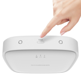
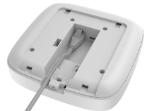
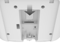
- Insert the charging cable into the home security hub and turn on the power switch. Wait a moment until the center indicator starts flashing green continuously.
.jpg)
- If the green indicator does not begin to flash within two minutes, please press and hold the "Cloud" button on the top of Home Security Hub for 5 seconds until the indicator begins flashing.
Go to the home page and then click "+" to add the home security hub by scanning the QR codes on device or on the packaging.
You can connect the device to the Internet in the following ways:
Wi-Fi:
Connect Wi-Fi by following the instructions in the App.
Ethernet or Cellular Network:
Connect to the Internet by plugging in a network cable or inserting a SIM card.When the network connection is functioning properly, the hub can automatically connect to the cloud platform without any additional user intervention.
Note : It recommended to apply all the three network methods when using the system, to work against network failure
The Cloud Indicator turns blue when the connection is successful.

- The Home Security Hub is added successfully , you can rename the device.
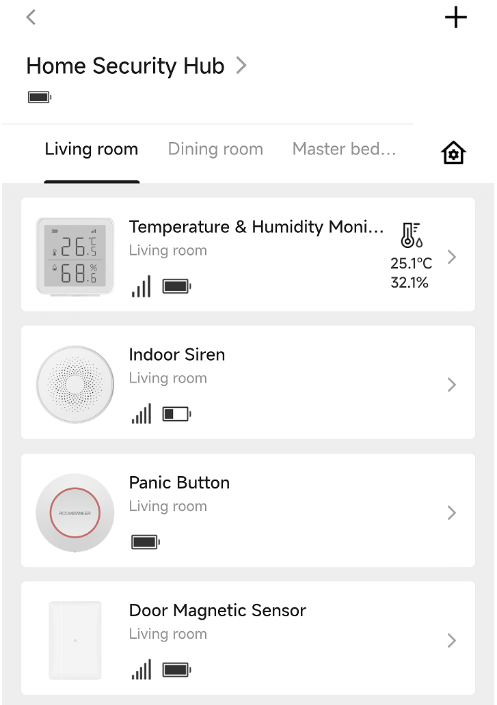
2.3 Home Page Display
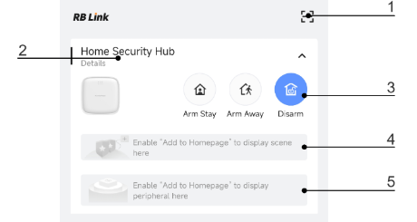
- Add the hub by scanning the QR code.
- Click to enter the management page of the hub.
- Quick Arming / Disarming.
- Custom scenes display area.
- Peripherals display area.
2.4 Hub Status Introduction
2.4.1 Hub icons
Icons display some of the Hub status.
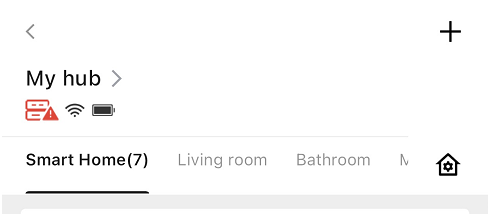
| Icon | Value |
|---|---|
 | The icon indicates that the hub is currently connected to the cloud server via Wi-Fi. |
 | The icon indicates that the hub is currently connected to the cloud server via Ethernet. |
 | The icon indicates that the hub is currently connected to the cloud server via Cellular Network. |
| This icon indicates an issue with the system or peripherals. Tap for details. | |
 | Lithium Battery Level |
 | Room management. For more information, please turn to Charter 3. Room Management. |
Ethernet>Wi-Fi>Cellular Network. It will only show the icon of the networking method that is currently in use.
2.4.2 Hub status
Hub states can be viewed in the RB Link (App).
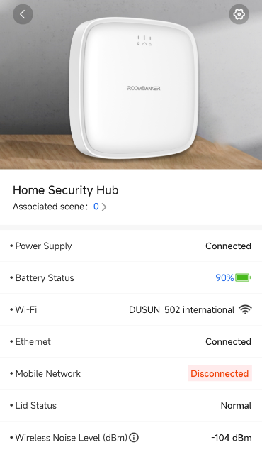
| Parameter | Meaning |
|---|---|
| Associated scene | The number of scenes associated with Hub |
| Power Supply | The current status of the hub's power supply Connected - the hub is connected to power supply Disconnected - no power supply is available |
| Ethernet | Internet connection status of the hub via Ethernet: Connected - The hub can connect to the cloud via Ethernet Disconnected - The hub cannot connect to cloud via Ethernet |
| Wi-Fi | Internet connection status of the hub via Wi-Fi,tap here to access Wi-Fi settings.: - The hub can connect to cloud via Wi-Fi - The hub can connect to cloud via Wi-Fi - The hub cannot connect to cloud via Wi-Fi - The hub cannot connect to cloud via Wi-Fi |
| Mobile Network | The hub connection status to the mobile Internet: Connected - The hub can connect to the cloud via Cellular Network. Disconnected - The hub cannot connect to cloud via Cellular Network |
| Battery Status | Battery level of the device |
| Lid Status | Status of the tamper that responds to hub dismantling: Normal - The hub is installed on the back panel Triggered - The hub is removed from back panel |
| Wireless Noise Level (dBm) | The surrounding environment will affect the noise level of hub. lt is recommended that you install an environment where the noise level is in the range of -128 ~ -95 dBm. |
2.5 Hub Setting
You can click " " on the top right corner of the hub to configure parameters.
2.5.1 Basic Information
| Parameter | Meaning |
|---|---|
| Device name | Click on the device name and enter the a nickname if it's in need. |
| Device model | Display the device model. |
| IP Address | Display the IP address of the device. |
| MAC Address | Display the MAC address of the device. |
| Serial Number | Display the serial number of the device. |
| Version Number | The current firmware version of the device is displayed here. If a new version is available, you can simply click to upgrade via OTA. |
2.5.2 User Management
Please turn to Charter 5. User Management for more details about user management.
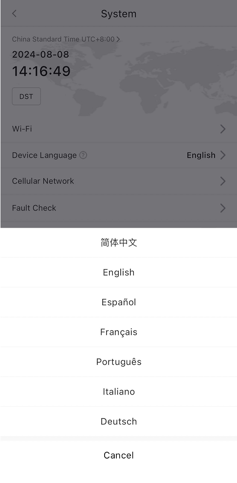
2.5.3 System
Time Zone
Click ">" and then select your time zone, then the time will be updated automatically.

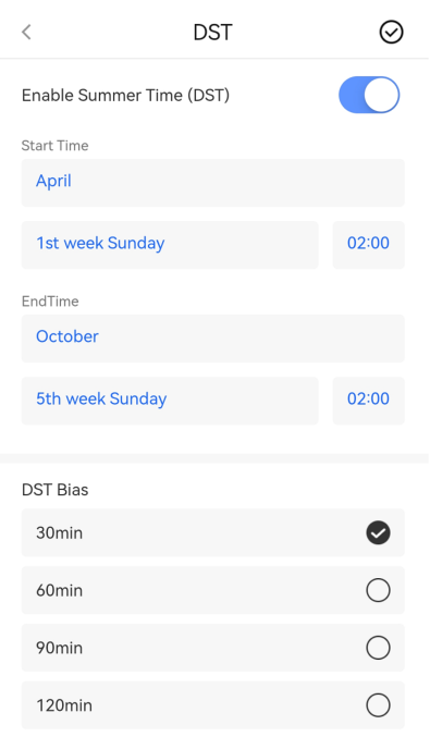
DST
Click"DST", you can enable or disable Daylight Saving Time, set start and end times, and save the settings, the time will update accordingly.
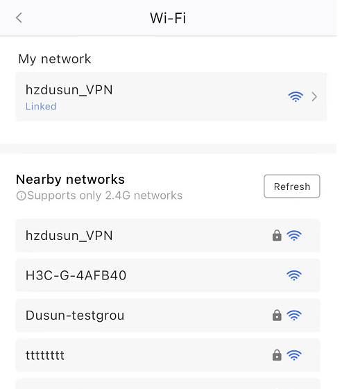
- Wi-Fi
Tap to reconfigure Wi-Fi.
- Device Language
After Setting the language, SMS will be displayed in this language.
Cellular Network
Username, Password and APN - After inserting the SIM card, the Hub automatically obtains the necessary information and connects to the network. If you are unable to connect, please contact your telecom operator to obtain these information and perform manual configuration.
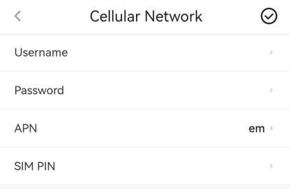
SIM PIN - If the system prompts that the SIM PIN is not configured, enter the SIM PIN to use the SIM card. If your SIM card is locked, please try to contact your telecom operator to unlock it.

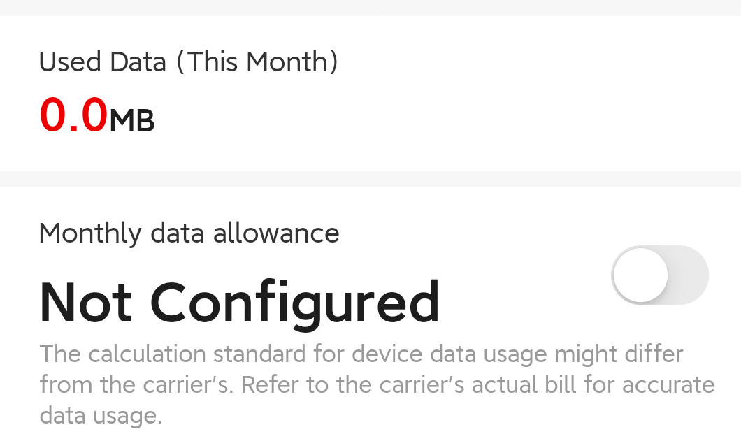
Used Data (This month) - Show current data usage.
Monthly data allowance - You can set a data usage limit here, and the App will send a notification when that limit is exceeded.
Fault Check
You can configure fault detection rules. After you enable it, the Hub performs periodic detection and uploads relevant information according to the configured rules.
| Parameter | Meaning |
|---|---|
| Battery Loss | Monitors battery connection status to ensure it's functioning normally. Open - Monitoring function is active Close - Monitoring function is disabled |
| Low Battery | Monitors low battery levels (below 20%) Open - Monitoring function is active Close - Monitoring function is disabled |
| Ethernet Lost | Monitors ethernet connectivity, and sends an alert to the APP if an ethernet outage lasts longer than a predefined threshold. |
| Wi-Fi Lost | Monitors Wi-Fi connectivity, and sends an alert to the APP if Wi-Fi outage lasts longer than a predefined threshold. |
| Cellular Network Lost | Monitors Cellular Network connectivity, and sends an alert to the APP if Cellular Network outage lasts longer than a predefined threshold. |
| External Power Lost | Monitors external power supply connection status Open - Monitoring function is active Close - Monitoring function is disabled |
24H Lid Detection
This feature is disabled by default, detecting hub tampering and triggering an alarm if disassembly is detected. It can be used in both armed and disarmed states.
Wire Network Configuration
Static IP Settings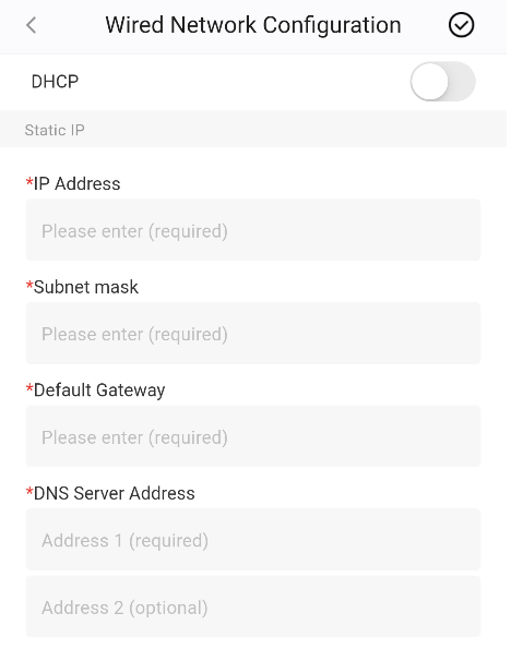
When using a static IP (instead of DHCP), manually enter:
| Parameter | Meaning |
|---|---|
| IP Address | The unique identifier of the device on the network (e.g. 192.168.1.100). It must be in the same subnet as your router/gateway and not conflict with other devices. |
| Subnet Mask | Defines the network and host portions of the IP address. Common value: 255.255.255.0 (equivalent to /24 subnet). |
| Default Gateway | Typically the router's IP address (e.g. 192.168.1.1), used for accessing external networks such as the internet. |
| DNS Server Address | The Domain Name System (DNS) server address for resolving domain names (e.g. 8.8.8.8 or 114.114.114.114). |
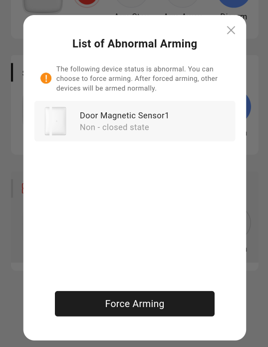
- Arming Check
Setting Path: Hub Settings → System → Arming Check (default: Off)
After turning on, when performing arming, if a sub-device has a fault, a confirmation reminder will pop up.Please note that when arming via keyfob or keypad, if any sensor malfunctions, you need to press the arming button on the keyfob or keypad again for secondary confirmation.
1.When arming via the mobile app, a secondary confirmation dialog pops up; arming only succeeds after the user confirms and dismisses this prompt.
2.When arming with the keyfob, the keyfob’s LED flashes red for 10 seconds. If you press the Arm button again within 10 seconds, arming is successful; otherwise, it fails.
3.When arming with the keypad, the keypad’s LED flashes red for 10 seconds. If you press the Arm button again within 10 seconds, arming is successful; otherwise, it fails.
2.5.4 Communication
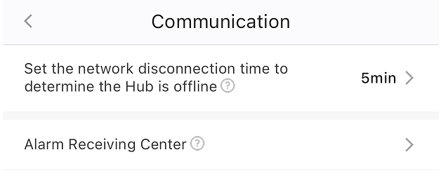
- Hub offline timeout
During this period, if your Hub is frequently online and offline, you will not receive any offline notifications. Due to delay or status synchronization, the delay time may be different.
- Alarm Receiving Center
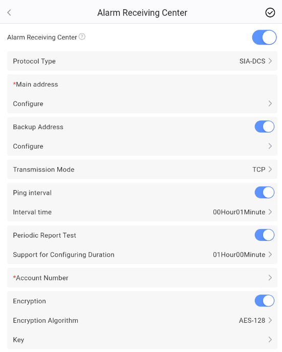
Once you subscribe to the Alarm Receiving Center (ARC) service, your installer or the ARC will provide you with the necessary information, as shown in the image. After entering and saving this information, your ARC service will be activated. Any alarm triggered in your home will be immediately reported to the ARC.
| Parameter | Meaning |
|---|---|
| Protocol Type | SIA or CID |
| Main Address | Primary IP Address & Port: (Required) |
| Backup Address | Secondary IP Address & Port: (Optional) |
| Transmission Mode | TCP or UDP |
| Ping Interval | Heartbeat Interval: (Optional, configurable if enabled) |
| Periodic Report Test | support for configuring duration:1min ~ 23h59min,default value 1h. (Optional, configurable if enabled) |
| Account Number | Assigned by ARC |
| Encryption | AES-128, AES-192, or AES-256 with corresponding key(Optional) |
2.5.5 Maintenance
Walk Test
Enable walk test, you can trigger the corresponding sensors individually in order to check if they are installed and configured correctly. When this function is enabled, only the indicators in sensors will flash red instead of pushing alarm notification. and you can also see the corresponding status changes from
Not TriggeredtoTriggeredif the sensor detects an alarm event.
Firmware Upgrade
The current firmware version of the device is displayed here. If a new version is available, you can simply click to upgrade.
Device Reset
- Restart Hub - Click
Restartbutton to restart the hub without changing any settings. - Factory Default - Click
Restorebutton to reset all settings to their factory defaults. - Reset Network - Click
Defaultbutton to reset the network settings while preserving detectors and peripherals.
- Restart Hub - Click
SSH
When SSH is enabled, our technical support staff can help you troubleshoot issues with your device remotely. SSH is disabled by default and can only be enabled by you and other Admin users.
2.5.6 User Guide
You can click to view the Quick Start Guide document of the Hub (R2 / R2 PRO).
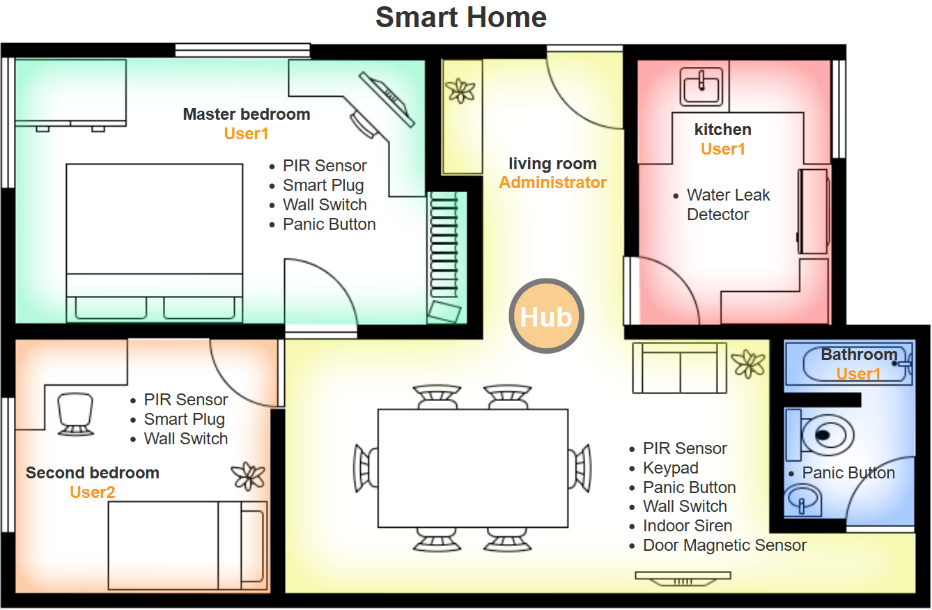
Charter 3. Room Management
● Definition of Room: the area where the peripheral is installed in house.
● Function of Room: allow each peripheral to be assigned to just one room. Admins can assign management permissions to different users on different rooms.
3.1 Create a room
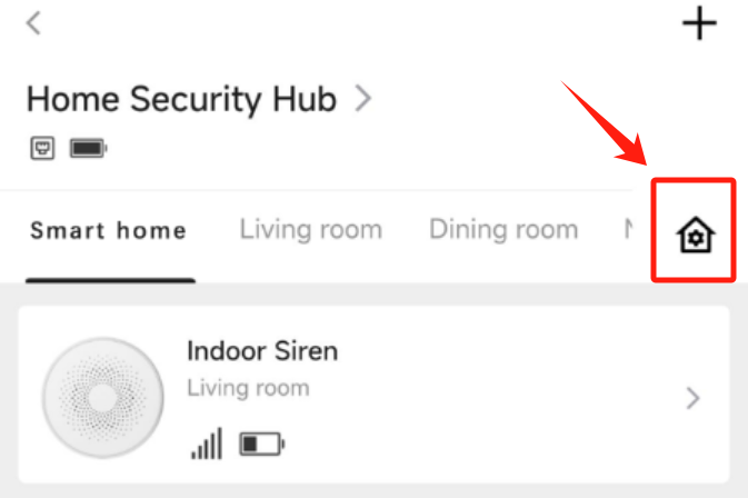
Click "" on the management page of Hub to view your rooms.
Click Create a New Room to add a new room, you can fill in the room name by yourself or choose one of the recommended name generated by app.
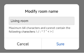
3.2 Rename a room
Click a room whose name you want to modify, then you can edit its name by yourself.
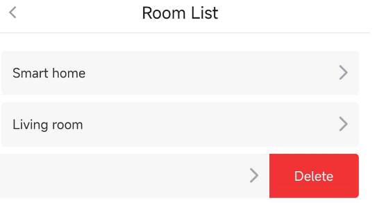
3.3 Delete a room
Deleting a room is a snap. Just swipe left on the room in the list and click Delete.
3.4 View Peripherals in a specific room
In the Hub management page, click on a specific room to view all the associated peripherals.
Charter 4. Peripheral Setting
4.1. Adding peripherals
Home Security System supports 2 types of wireless peripheral adding:
● By QR Code: adding peripherals one by one.
● By Enrollment Mode: adding multiple peripherals in bulk.
Option 1: Adding via QR Code
This is a way to add your wireless peripherals (RBF) one by one by scanning device QR Code. And QR Code can be found on device or device package. Please refer to the following guide to add your peripheral via QR Code.
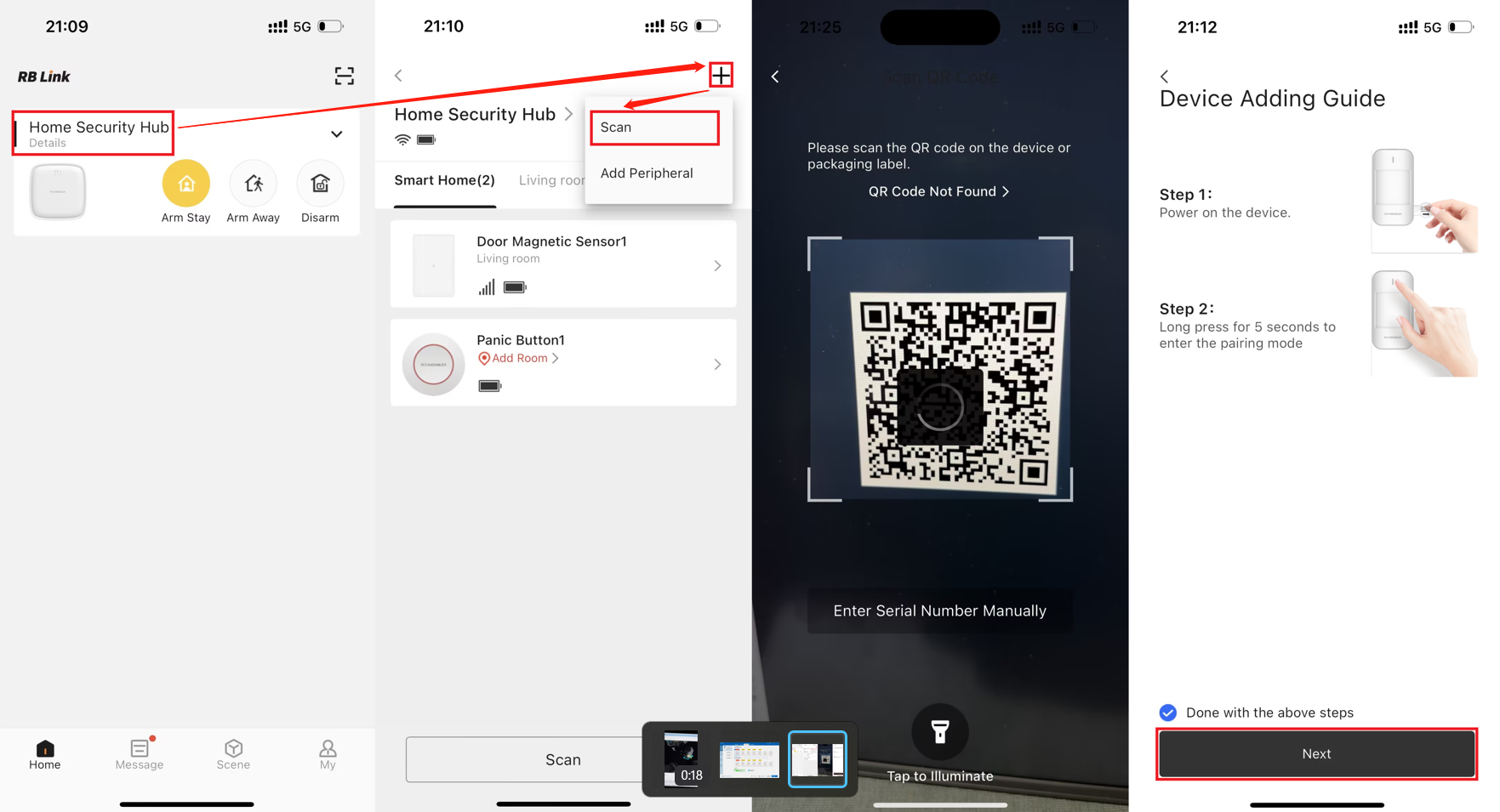
- Open RB Link App. Click name of your hub to turn to the "Main Page" of your hub.
- Click
+icon on the top right corner, and then clickScanto open your phone's camera to scan device QR Code. - When QR Code is scanned, App will turn to Device Adding Guide page, you can follow the guide to operate your device and click
Nextto wait for adding. - When your device is added, please assign a room for this device and edit the device name.
- Click
Doneto finish adding.
After all above steps, your device will show up on the product list of the assigned room or on the product list of Smart Home.
- Only the RBF peripherals (with "
" printed on their packages) support to be added via QR Code, while Bluetooth and Zigbee peripherals doesn't work.
- Since wall switch needs to connect to mains power (110V~ / 220V~) as a power supply, it is recommended to use "Adding via Scan QR Code" before cable connection.
Option 2: Adding via Enrollment Mode
To batch add devices, tap "Add Peripheral" on the home page, follow the video instructions to put your devices into enrollment mode, and they will be automatically added to the App.
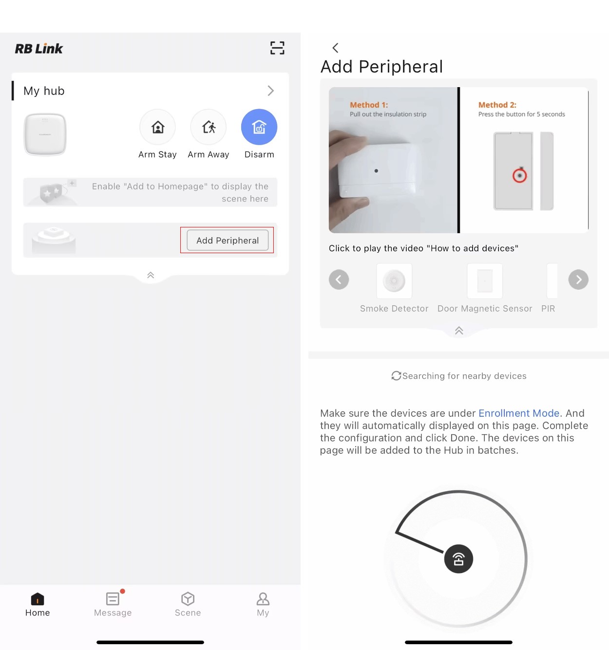
- All the rest devices except Wall Switch are recommended to use "Adding via Enrollment Mode".
- Keyfob needs to be assigned to a user after enrolled.
- Keypad needs to be set which rooms can be controlled after enrolled.
4.2 Peripheral Icons
| Icon | Meaning |
|---|---|
 | Device signal strength between the wireless peripherals and hub. |
 | Device battery status. Red means low battery |
 | Alarm triggered, including device alarm and tamper alarm. |
 | PIR Motion alarm triggered. *for PIR Sensor only. |
 | Water Leak alarm triggered. *for Water Leak Detector only. |
 | Smoke alarm triggered. *for Smoke Detector only. |
 | Solar Panel is charging the battery. *for Outdoor Siren only |
4.3 PIR Sensor
*You can click Spec and QSG to check more information about PIR sensors.
4.3.1 Appearance
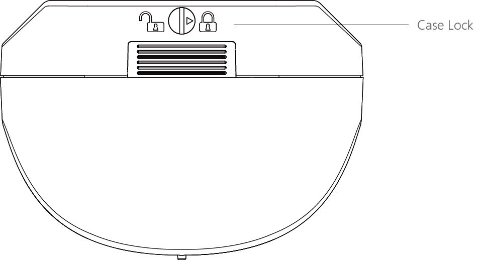
| Appearance | Description |
|---|---|
| LED Indicator | Red / Green / Orange *Used to indicate alarm status, signal strength status, and Find Me status. |
| Register Button | Press and hold for 5s to add the PIR to the Hub. *Register Button is only used for re-adding or connecting the peripheral to another hub. |
| PIR Lens | Fresnel lens *Used to detect motion within the detection range. |
| Case Lock | Rotate to lock / unlock the PIR case. |
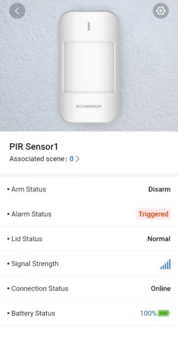
4.3.2 State
| Parameter | Value | Meaning |
|---|---|---|
| Associated scene | 0 ~ 64 | Shows the number of custom scenes associated with this PIR. You can also click to view and configure the scenes. *Please turn to Charter 6. Scene Management for more details. |
| Arm Status | Arm / Disarm | Shows the arm status of the PIR. When it’s armed, the PIR could detect motion events and then report alarm to Hub immediately. *The PIR will enter sleep mode for energy-saving. |
| Alarm Status | Normal / Alarm | Shows whether the PIR is triggered. *Alarm will only be triggered when PIR is armed. |
| Lid Status | Normal / Triggered | Shows whether the lid of PIR is open or not. |
| Signal Strength |  | Shows the signal strength between the PIR and the hub. |
| Connection Status | Online / Offline | Shows the connection status between the PIR and the Hub. *The PIR will not be functional if the status is offline. |
| Battery Status |  | Shows the battery level of PIR. *If the battery level is low, the icon will turn red and you’ll receiver a malfunction notification in App. |
4.3.3 Setting
Click "" on the top right corner and turn to “Setting”.

| Parameter | Value | Meaning |
|---|---|---|
| Basic Information | / | Check the basic information of this device, including MAC Address, Serial Number, etc. And you can also edit the device name here by yourself. |
| Add Room | 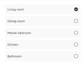 | You can select one of the rooms created before and then link the PIR to. *When linked to a specific room, the PIR will be displayed on the product list of the room, and the PIR could begin for detecting when the room is armed. |
| Find Me |  | A function that used to find your PIR among numerous devices. When you enable this function, the indicator in PIR will flash green to help you find the target device quickly. |
| Signal Strength Test | 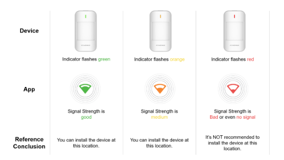 | A function that used to check the signal strength between PIR and hub at the tested place, which is designed to help you choose the right place for installation. When you enable this function, you can check the signal strength by watching the indicator in PIR and the feedback in app. |
| Installation Test |  | A function that used to test whether the PIR is installed properly. When you enable this function, you can walk in the room to test if the PIR can detect and trigger an alarm properly. The indicator will flash red when it detects successfully. |
| Tamper detection | ON / OFF | When the tamper detection is enabled, if the tamper switch is triggered while the hub is armed, an alarm will be triggered. PIR must install the cardan bracket to make "Tamper Detection" effective. |
| Detection Sensitivity | High / Medium / Low | Adjust sensitivity per actual installation environment to cut false & missed alarms and boost detection accuracy. |
| Firmware Upgrade | The device supports firmware upgrade functionality and can be updated remotely over the air. The system periodically checks for version updates, allowing users to download and install firmware updates via the mobile app when the Hub is connected to the internet. | |
| Disable Device | ON / OFF | If this button is ON, the alarm and malfunctions generated by this PIR will no longer be uploaded to the Hub and App. *It is recommended that you disable the device only if it’s defective. Before turning on this function, please ensure that you are aware of the situation to avoid possible personal injury or property damage that may result from the device not detecting and triggering an alarm. |
| Display On Homepage | ON / OF | When enabled, the PIR will show up on homepage so that you can operate quickly. |
| User Guide | / | Click to check the user guide document of PIR. |
| Delete Device | / | Delete the PIR from your hub. |
| 24-hour Alarm | ON / OF | Enable the PIR Sensor to be armed 24h,it will trigger an alarm whenever activated. |
4.4 Door Window Sensor
*You can click Spec and QSG to check more information about Door Window Sensor.
4.4.1 Appearance
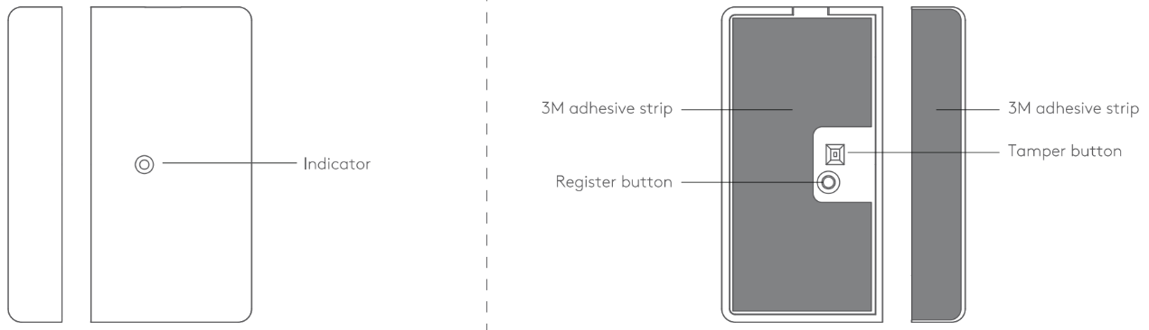
| Appearance | Description |
|---|---|
| LED Indicator | Red / Green / Orange *Used to indicate alarm status, signal strength status, and Find Me status. |
| Register Button | Press and hold for 5s to add the Door Window Sensor to the Hub. *Register Button is only used for re-adding or connecting the peripheral to another hub. |
| Tamper Switch / Tamper Button | Used to detect the tamper alarm status of the lid. |
4.4.2 State
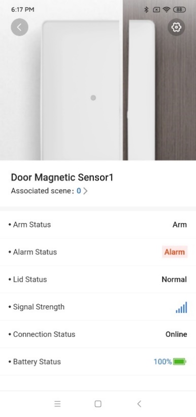
| Parameter | Value | Meaning |
|---|---|---|
| Associated scene | 0 ~ 64 | Shows the number of custom scenes associated with this Door Window Sensor. You can also click to view and configure the scenes. *Please turn to Charter 6. Scene Management for more details. |
| Arm Status | Arm / Disarm | Shows the arm status of the Door Window Sensor. When it’s armed, the Door Window Sensor could detect open/close events and then report alarm to Hub immediately. |
| Alarm Status | Normal / Alarm | Shows whether the Door Window Sensor is triggered. |
| Lid Status | Normal / Triggered | Shows whether the Door Window Sensor’s lid is opened or not. |
| Signal Strength | | Shows the signal strength between the Door Window Sensor and the Hub. |
| Connection Status | Online / Offline | Shows the connection status between the Door Window Sensor and the Hub. *The Door Window Sensor will not be functional if the status is offline. |
| Battery Status | | Shows the battery level of Door Window Sensor. *If the battery level is low, the icon will turn red and you’ll receive a malfunction notification in App. |
4.4.3 Setting
Click "" on the top right corner and turn to “Setting”.
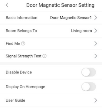
| Parameter | Value | Meaning |
|---|---|---|
| Basic Information | / | Check the basic information of this device, including MAC Address, Serial Number, etc.And you can also edit the device name here by yourself. |
| Room Belongs to |  | You can select one of the rooms created before and then link the Door Window Sensor to. *When linked to a specific room, the Door Window Sensor will be displayed on the product list of the room, and the alarm will be triggered only when the room is armed. |
| Find Me |  | A function that used to find your Door Window Sensor among numerous devices. When you enable this function, the indicator in Door Window Sensor will flash green to help you find the target device quickly. |
| Signal Strength Test | 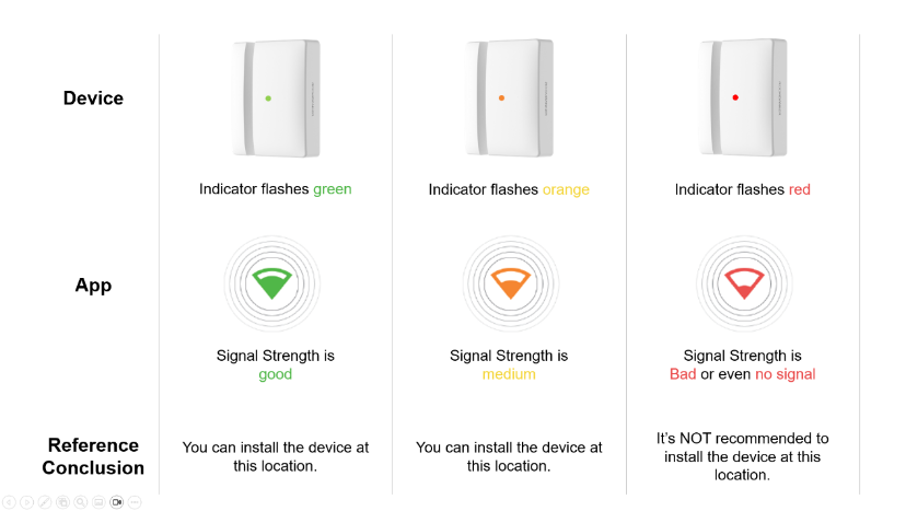 | A function that used to check the signal strength between Door Window Sensor and hub at the tested place, which is designed to help you choose the right place for installation. When you enable this function, you can check the signal strength by watching the indicators in Door Window Sensor and the feedback in app. |
| Installation Test |  | A function that used to test whether the Door Window Sensor is installed properly. When you enable this function, you can open the door or window to test if the Door Window Sensor can detect and trigger an alarm properly. The indicator will flash red when it detects successfully. |
| Disable Device | ON / OFF | If this button is ON, the alarm and malfunctions generated by this Door Window Sensor will no longer be uploaded to the Hub and App. *It is recommended that you disable the device only if it’s defective. Before turning on this function, please ensure that you are aware of the situation to avoid possible personal injury or property damage that may result from the device not detecting and triggering an alarm. |
| Display On Homepage | ON / OFF | When enabled, the Door Window Sensor will show up on homepage so that you can operate quickly. |
| User Guide | / | Click to check the user guide document of Door Window Sensor. |
| Delete Device | / | Delete the Door Window Sensor from your hub. |
| 24-hour Alarm | ON / OF | Enable the Door Window Sensor to be armed 24h,it will trigger an alarm whenever activated. |
4.5 Panic Button
*You can click Spec and QSG to check more information about Panic Button.
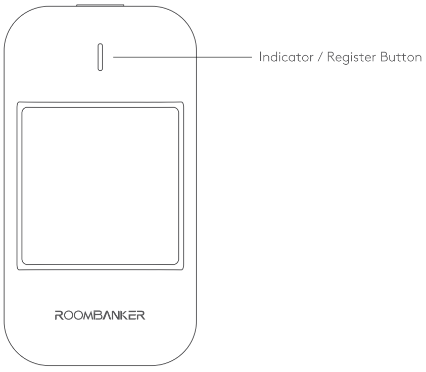
4.5.1 Appearance
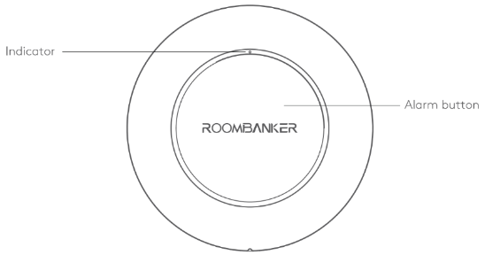
| Appearance | Description |
|---|---|
| LED Indicator | Red / Green / Orange *Used to indicate alarm status, signal strength status, and Find Me status. |
| Alarm Button | 1. Press to trigger panic alarm. 2. Press and hold for 10s to enter paring mode. *Paring mode is only used for re-adding or connecting the Panic Button to another Hub. |
4.5.2 State
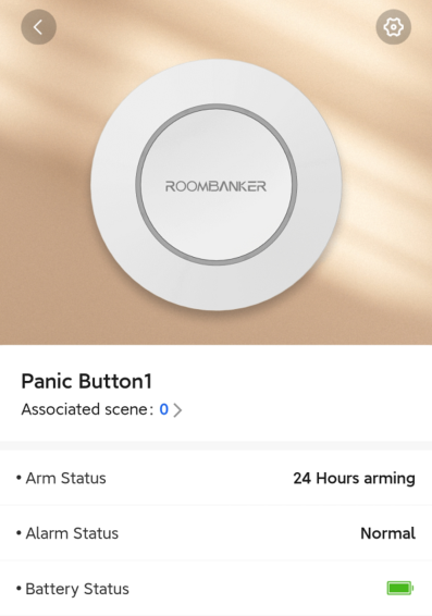
| Parameter | Value | Meaning |
|---|---|---|
| Associated scene | 0 ~ 64 | Shows the number of custom scenes associated with this Panic Button. You can also click to view and configure the scenes. *Please turn to Charter 6. Scene Management for more details. |
| Arm Status | 24 Hours arming | Panic Button is functional for 24/7, no matter the system is armed or not. |
| Alarm Status | Normal / Alarm | Shows whether the Panic Button is pressed or not. |
| Battery Status | | Shows the battery level of Panic Button. |
4.5.3 Setting
Click "" on the top right corner and turn to “Setting”.
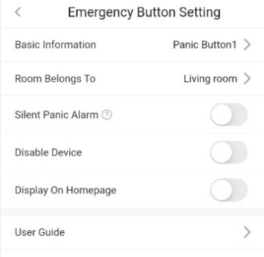
| Parameter | Value | Meaning |
|---|---|---|
| Basic Information | / | Check the basic information of this device, including MAC Address, Serial Number, etc. And you can also edit the device name here by yourself. |
| Room Belongs to | | You can select one of the rooms created before and then link the Panic Button to. *When linked to a specific room, the Panic Button will be displayed on the product list of the room. |
| Find Me | 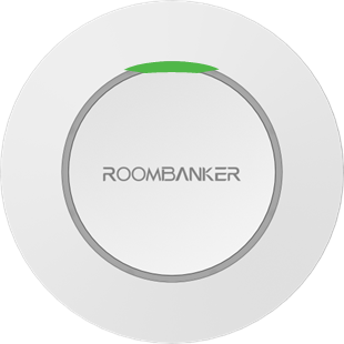 | A function that used to find your Panic Button among numerous devices. When you enable this function, the indicator in Panic Button will flash green to help you find the target device quickly. |
| Signal Strength Test | 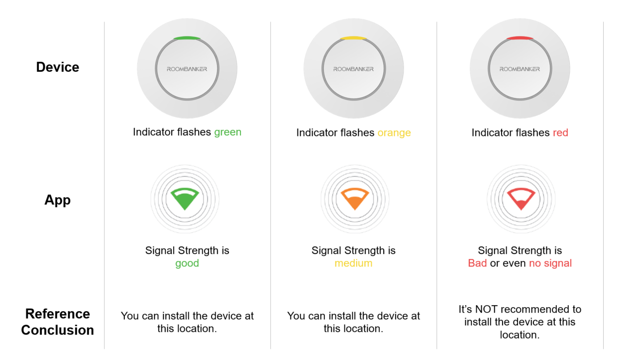 | A function that used to check the signal strength between Panic Button and hub at the tested place, which is designed to help you choose the right place for installation. |
| Silent Panic Alarm | ON / OFF | When enabled, panic alarm triggered with no alarm sound from the linked siren. |
| Disable Device | ON / OFF | When enabled, the Panic Button will be disabled. |
| Display On Homepage | ON / OFF | When enabled, the Panic Button will show up on homepage. |
| User Guide | / | Click to check the user guide document of Panic Button. |
| Delete Device | / | Delete the Panic Button from your hub. |
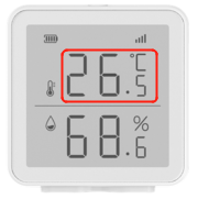
4.6 Temperature Humidity Monitor
*You can click Spec and QSG to check more information about Temperature Humidity Monitor.
4.6.1 Appearance
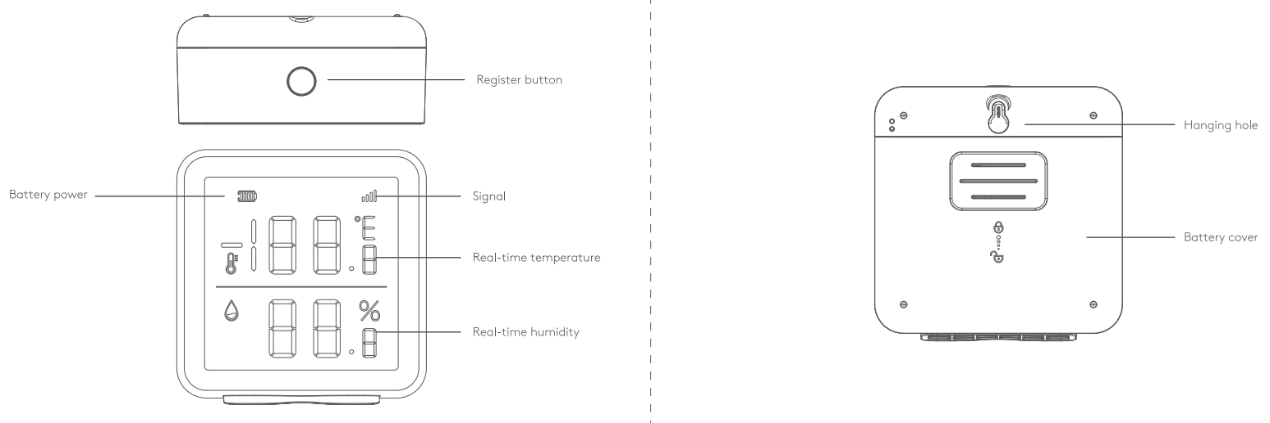
| Appearance | Description |
|---|---|
| Register Button | Press and hold for 5s to enter paring mode. *Used to add Temperature Humidity Monitor to the hub. |
| Battery icon | Shows the battery level of this Temperature Humidity Monitor. |
| Signal icon | Shows the signal strength between Temperature Humidity Monitor and hub. |
| Temperature | Shows the temperature of the installation place. |
| Humidity | Shows the humidity of the installation place. |
| Hanging hole | Used to hang the Temperature Humidity Monitor to the wall. |
| Battery cover | Slide to open and replace the AA batteries. |
4.6.2 State
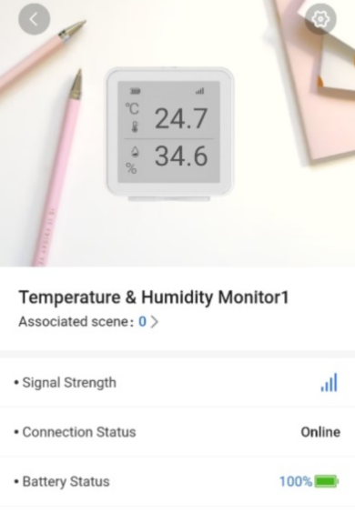
| Parameter | Value | Meaning |
|---|---|---|
| Associated scene | 0 ~ 64 | Shows the number of custom scenes associated with this Temperature&Humidity Monitor. You can also click to view and configure the scenes. *Please turn to Charter 6. Scene Management for more details. |
| Signal Strength | | Shows the signal strength between Temperature&Humidity Monitor and hub. |
| Connection Status | Online / Offline | Shows the connection status between the Temperature&Humidity Monitor and the Hub. The Temperature Humidity Monitor will not be functional if the status is offline.* |
| Battery Status | | Shows the battery level of Temperature&Humidity Monitor. *If the battery level is low, the icon will turn red and you’ll receiver a malfunction notification in App. |
4.6.3 Setting
Click "" on the top right corner and turn to “Setting”.
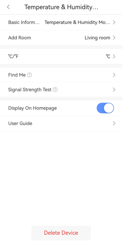
| Parameter | Value | Meaning |
|---|---|---|
| Basic Information | / | Check the basic information of this device, including MAC Address, Serial Number, etc. And you can also edit the device name here by yourself. |
| Add Room | | You can select one of the rooms created before and then link the Temperature Humidity Monitor to. When linked to a specific room, the Temperature Humidity Monitor will be displayed on the product list of the room. |
| ℃/℉ |  | A function that used to toggle between Celsius and Fahrenheit displays. |
| Find Me | 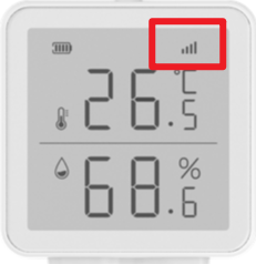 | A function that used to find your Temperature&Humidity Monitor among numerous devices. |
| Signal Strength Test | 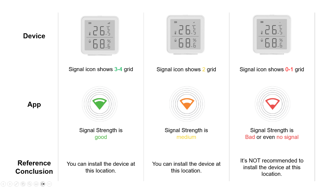 | A function that used to check the signal strength between Temperature Humidity Monitor and hub at the tested place, which is designed to help you choose the right place for installation. |
| Display On Homepage | ON / OFF | When enabled, the Temperature Humidity Monitor will show up on homepage. |
| User Guide | / | Click to check the user guide document of Temperature Humidity Monitor. |
| Delete Device | / | Delete the Temperature Humidity Monitor from your hub. |
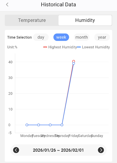
4.6.4 Key Features
Temperature and humidity sensors can display data in four dimensions: daily, week, month and year.
4.7 Water Leak Detector
*You can click Spec and QSG to check more information about Water Leak Detector.
4.7.1 Appearance
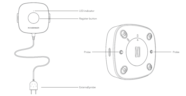
| Appearance | Description |
|---|---|
| LED Indicator | Red / Orange / Green. *Used to indicate alarm status, signal strength status, and Find Me status |
| Register Button | Press and hold for 5s to add the Water Leak Detector to the Hub. *Register Button is only used for re-adding or connecting the peripheral to another hub. |
| Probe | Detects water leaks by detecting whether the two probes are shorted by water. |
| External Probe | Optional for expanding an additional detection point for water leaking detection. |
4.7.2 State
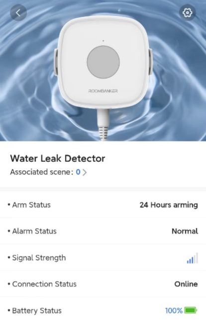
| Parameter | Value | Meaning |
|---|---|---|
| Associated Scene | 0 ~ 64 | Shows the number of custom scenes associated with this Water Leak Detector. You can also click to view and configure the scenes. *Please turn to Charter 6. Scene Management for more details. |
| Arm Status | 24 Hours Arming | Water Leak Detector keeps detecting for 24/7, no matter the system is armed or disarmed. |
| Alarm Status | Normal / Alarm | Shows whether the Water Leak Detector is triggered. |
| Signal Strength | | Shows the signal strength between the Water Leak Detector and the Hub. |
| Connection Status | Online / Offline | Shows the connection status between the Water Leak Detector and the Hub. *The Water Leak Detector will not be functional if the status is offline. |
| Battery Status | | Shows the battery level of Water Leak Detector. *If the battery level is low, the icon will turn red and you’ll receive a malfunction notification in App. |
4.7.3 Setting
Click "" on the top right corner and turn to “Setting”.
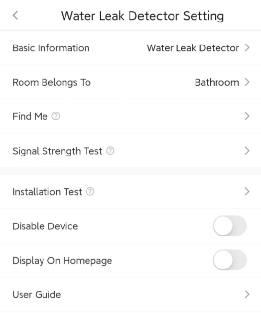
| Parameter | Value | Meaning |
|---|---|---|
| Basic Information | / | Check the basic information of this device, including MAC Address, Serial Number, etc.And you can also edit the device name here by yourself. |
| Room belongs to | | You can select one of the rooms created before and then link the Water Leak Detector to.***When linked to a specific room, the Water Leak Detector will be displayed on the product list of the room. |
| Find Me |  | A function that used to find your Water Leak Detecotr among numerous devices.When you enable this function, the indicator in Water Leak Detector will flash green to help you find the target device quickly. |
| Signal Strength Test | 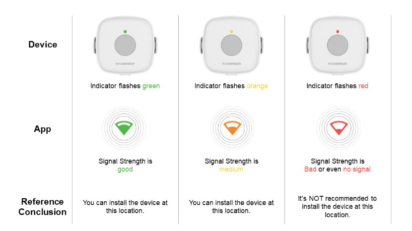 | A function that used to check the signal strength between Water Leak Detector and hub at the tested place, which is designed to help you choose the right place for installation. When you enable this function, you can check the signal strength by watching the indicator in Water Leak Detector and the feedback in app. |
| Installation Test |  | A function that used to test whether the Water Leak Detector is installed properly.When you enable this function, you can simulate a water leaking event to test if the Water Leak Detector can detect and trigger an alarm properly. The indicator will flash red when it detects successfully. |
| Disable Device | ON / OFF | If this button is ON, the alarm and malfunctions generated by this Water Leak Detector will no longer be uploaded to the Hub and App.*It is recommended that you disable the device only if it’s defective. Before turning on this function, please ensure that you are aware of the situation to avoid possible personal injury or property damage that may result from the device not detecting and triggering an alarm. |
| Display On Homepage | ON / OFF | When enabled, the Water Leak Detector will show up on homepage so that you can operate quickly. |
| User Guide | / | Click to check the user guide document of Water Leak Detector. |
| Delete Device | / | Delete the Water Leak Detector from your Hub. |
4.8 Smoke Detector
*You can click Spec and QSG to check more information about Smoke Detector.
4.8.1 Appearance
| Appearance | Description |
|---|---|
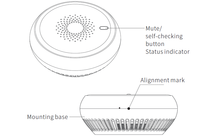
| Mute / Self-checking Button | Press and hold for 5s to add the Smoke Detector to the Hub. Press and hold for less than 5s for self-checking. |
| Status Indicator | Red / Green. *Used to indicate alarm status and self-checking status. |
| Alignment Mark | Used to check whether the device is installed properly. *If the semicircles on the device and mounting base are aligned to form a circle, the product is installed properly |
| Mounting Base | Can be installed on the ceiling with screws or 3M sticker. |
4.8.2 State
| Parameter | Value | Meaning |
|---|---|---|
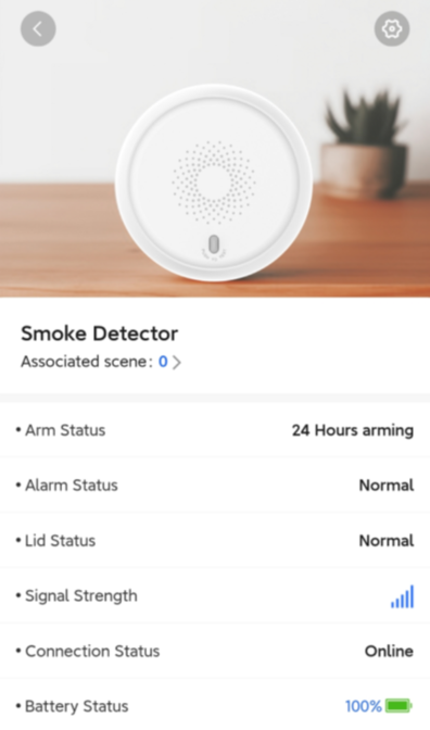
| Associated Scene | 0 ~ 64 | Shows the number of custom scenes associated with this Smoke Detector. You can also click to view and configure the scenes. *Please turn to Charter 6. Scene Management for more details. |
| Arm Status | 24 Hours Arming | Smoke Detector keeps detecting for 24/7, no matter the system is armed or disarmed. |
| Alarm Status | Normal / Alarm | Shows if there is alarm detected by Smoke Detector. |
| Lid Status | Normal / Triggered | Shows whether the lid of Smoke Detector is open or not. |
| Signal Strength | | Shows the signal strength between the Smoke Detector and the Hub. |
| Connection Status | Online / Offline | Shows the connection status between the Smoke Detector and the Hub. *The Smoke Detector will not be functional if the status is offline. |
| Battery Status | | Shows the battery level of Smoke Detector. *If the battery level is low, the icon will turn red and you’ll receiver a malfunction notification in App. |
4.8.3 Setting
Click "" on the top right corner and turn to “Setting”.
| Parameter | Value | Meaning |
|---|---|---|
| Basic Information | / | Check the basic information of this device, including MAC Address, Serial Number, etc.And you can also edit the device name here by yourself. |
| Room belongs to | | You can select one of the rooms created before and then link the Smoke Detector to. *When linked to a specific room, the device will be displayed on the product list of the room. |
| Disable Device | ON / OFF | If this button is ON, the alarm and malfunctions generated by this Smoke Detector will no longer be uploaded to the Hub and App. *It is recommended that you disable the device only if it’s defective. Before turning on this function, please ensure that you are aware of the situation to avoid possible personal injury or property damage that may result from the device not detecting and triggering an alarm. |
| Display On Homepage | ON / OFF | When enabled, the Smoke Detector will show up on homepage so that you can operate quickly. |
| User Guide | / | Click to check the user guide document of Smoke Detector. |
| Delete Device | / | Delete the Smoke Detector from your Hub. |
4.8.4 Test
When the device detects smoke, it will announce alarm by buzzing and flashing with built-in indicator and buzzer, and could also trigger sirens for alerting instantly if it’s connected to Hub, and the Hub will push alarm notifications to remote terminals via App, SMS, Phone Call, etc.
| Event | Indicator feedback | Buzzer feedback |
|---|---|---|
| Alarm is triggered | Red indicator flashes | Buzzer beeps |
| Work properly | Flashes once every 50 seconds | / |
| Battery power is low | Yellow indicator flashes once every 40 seconds. | Buzzer beeps shortly |
| Self-checking and alarm simulating state | Red indicator flashes. | Buzzer beeps 4 times. |
| Registration Mode (used to connect device into Hub) | Green indicator flashes. | / |
Alarm Test
Press the Mute/Self-checking button once, then the smoke detector enters self-checking mode, the indicator flashes red and the built-in buzzer beeps 4 times.
When alarm triggered, you can also press the Mute/self-checking button to mute the product.
Caution: In case of fire, please take proper measures immediately, such as calling the fire emergency number or using a fire extinguisher to put out of the fire.
Danger: Ignoring the fire alarm could result in property damage, personal injury, or even death. So please make sure there is no fire before you mute the detector.
4.9 Indoor Siren
*You can click Spec and QSG to check more information about Indoor Siren.
4.9.1 Appearance
| Appearance | Description |
|---|---|
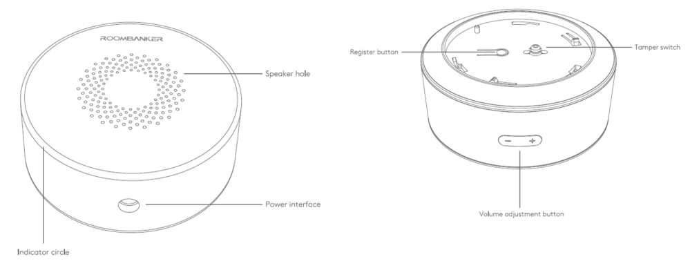
| Speaker Hole | Loudspeaker for buzzer. |
| Indicator Circle | Red / Orange / Green. *Used to indicate alarm status, Signal Strength status, and Find Me status. |
| Power Interface | Used to power the Indoor Siren with adapter. |
| Register Button | Press and hold for 5s to add the Indoor Siren to the Hub. *Register Button is only used for re-adding or connecting the peripheral to another hub. |
| Tamper Switch | Used to detect the tamper alarm status of the lid. |
| Volume Adjustment Button | Used to adjust the volume by manual. Switching among three options: 85 / 95 / 105 dB. |
4.9.2 State
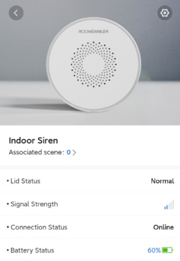
| Parameter | Value | Meaning |
|---|---|---|
| Associated Scene | 0 ~ 64 | Shows the number of custom scenes associated with this Indoor Siren. You can also click to view and configure the scenes. *Please turn to Charter 6. Scene Management for more details. |
| Lid Status | Normal / Triggered | Shows whether the lid of Indoor Siren is open or not. |
| Signal Strength | | Shows the signal strength between the Indoor Siren and the Hub. |
| Connection Status | Online / Offline | Shows the connection status between the Indoor Siren and the Hub. *The Indoor Siren will not be functional if the status is offline. |
| Battery Status | | Shows the battery level of Indoor Siren. *If the battery level is low, the icon will turn red and you’ll receiver a malfunction notification in App. |
4.9.3 Setting
Click "" on the top right corner and turn to “Setting”.
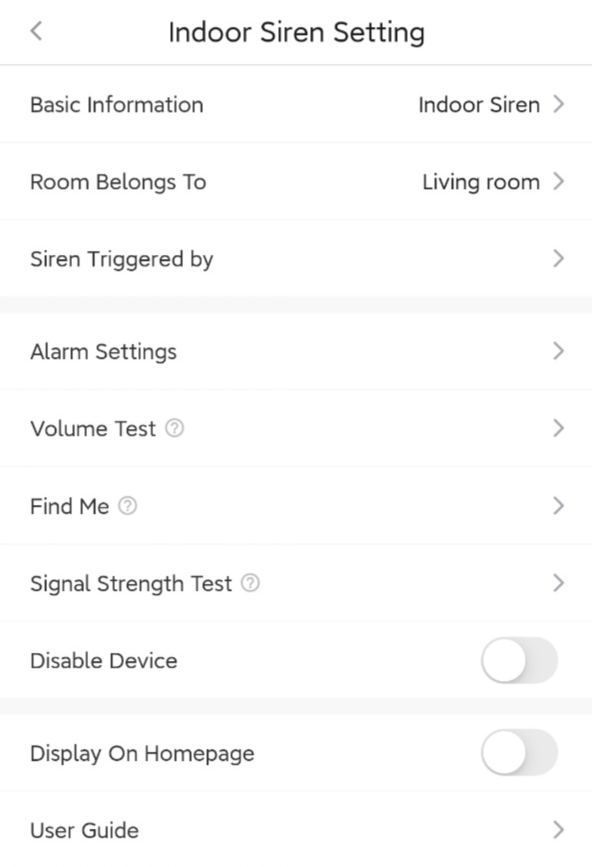
| Parameter | Value | Description |
|---|---|---|
| Basic Information | / | Check the basic information of this device, including MAC Address, Serial Number, etc. And you can also edit the device name here by yourself. |
| Room belongs to | 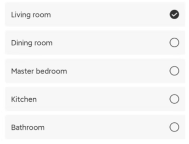 | You can select one of the rooms created before and then link the device to. *When linked to a specific room, the device will be displayed on the product list of the room. |
| Siren Triggered by | 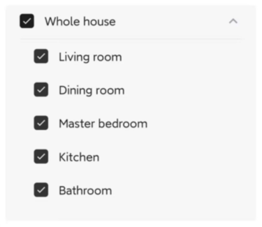 | The siren can be linked with one or multiple rooms as a warning device to announce any alarm or other events with sound and strobe. |
| Alarm Settings | 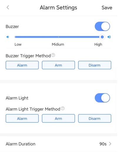 | Buzzer: 1. You can enable/disable buzzer and switch alarm volume among three levels: High (105dB) / Medium (95dB) / Low (85dB) 2. Buzzer Trigger Method: You can select one or more triggers. An alarm sound will be triggered when the following events occur. Alarm Light: 1. You can enable/disable alarm light manually. 2. Alarm Light Trigger Method: You can select one or more triggers. The siren strobe will be triggered when the following events occur. Alarm Duration: You can set the alarm duration of siren from 1s ~ 15mins. *90s by default |
| Volume Test | / | You can use it to check if the current volume could meet your requirement. |
| Find Me | 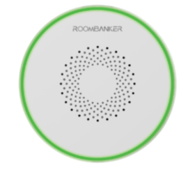 | A function that used to find your Indoor Siren among numerous devices. When you enable this function, the indicator in Indoor Siren will flash green to help you find the target device quickly. |
| Signal Strength Test | 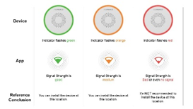 | A function that used to check the signal strength between the Indoor Siren and the hub at the tested place, which is designed to help you choose the right place for installation.When you enable this function, you can check the signal strength by watching the indicator in Indoor Siren and the feedback in app. |
| Disable Device | ON / OFF | If this button is ON, the alarm and malfunctions generated by this Indoor Siren will no longer be uploaded to the Hub and App. *It is recommended that you disable the device only if it’s defective. Before turning on this function, please ensure that you are aware of the situation to avoid possible personal injury or property damage that may result from the device not detecting and triggering an alarm. |
| Display On Homepage | ON / OFF | When enabled, the Indoor Siren will show up on homepage so that you can operate quickly. |
| User Guide | / | Click to check the user guide document of Indoor Siren. |
4.10 Outdoor Siren
*You can click Spec and QSG to check more information about Outdoor Siren.
4.10.1 Appearance
| Appearance | Description |
|---|---|
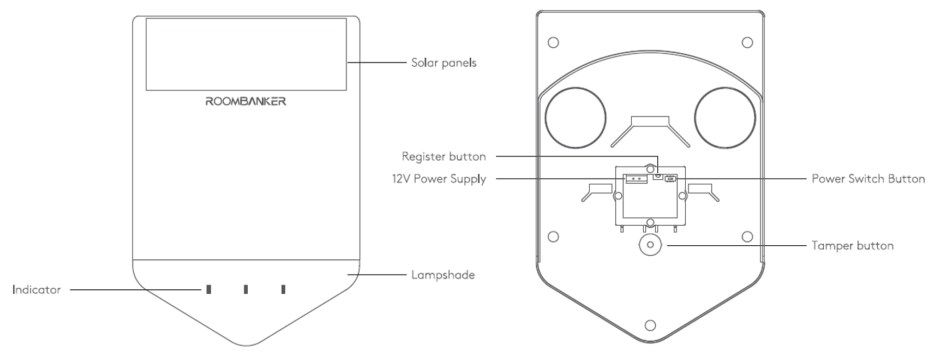
| Solar Panel | Solar panel for charging the built-in lithium battery. |
| Indicator | 3 LED indicators to announce alarm and other events. |
| Lampshade | *There are three options available for selection when placing orders (Red / Blue / Orange). |
| Register Button | Press and hold for 5s to add the Outdoor Siren to the Hub. *Register Button is only used for re-adding or connecting the outdoor siren to another Hub. |
| Power Switch Button | Used to turn ON/OFF the Outdoor Siren manually. |
| 12V Power Supply | Power supply interfaces are used for connecting 12 V DC power when it’s in need. |
| Tamper Button | Used to detect the tamper alarm status of the lid. |
4.10.2 State
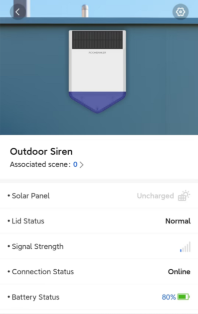
| Parameter | Value | Meaning |
|---|---|---|
| Associated Scene | 0 ~ 64 | Shows the number of custom scenes associated with this Outdoor Siren. You can also click to view and configure the scenes. *Please turn to Charter 6. Scene Management for more details. |
| Solar Panel | /  | Shows the charging status of solar panel. - Charging;- Uncharged. |
| Lid Status | Normal / Triggered | Shows whether the lid of Outdoor Siren is open or not. |
| Signal Strength | | Shows the signal strength between the Outdoor Siren and the Hub. |
| Connection Status | Online / Offline | Shows the connection status between the Outdoor Siren and the Hub. *The Outdoor Siren will not be functional if the status is offline. |
| Battery Status | | Shows the battery level of Outdoor Siren. *If the battery level is low, the icon will turn red and you’ll receiver a malfunction notification in App. |
4.10.3 Setting
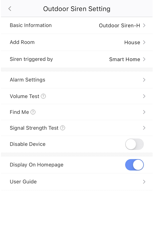
| Parameter | Value | Description |
|---|---|---|
| Basic Information | / | Check the basic information of this device, including MAC Address, Serial Number, etc. And you can also edit the device name here by yourself. |
| Add Room | | You can select one of the rooms created before and then link the device to. *When linked to a specific room, the device will be displayed on the product list of the room. |
| Siren Triggered by | | The siren can be linked with one or multiple rooms as a warning device to announce any alarm or other events with sound and strobe. |
| Alarm Settings | 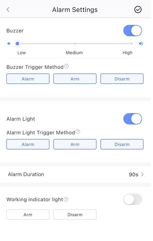 | Buzzer: 1. You can enable/disable buzzer and switch alarm volume among three levels: High (105dB) / Medium (95dB) / Low (85dB) 2. Buzzer Trigger Method: You can select one or more triggers. An alarm sound will be triggered when the following events occur. Alarm Light: 1. You can enable/disable alarm light manually. 2. Alarm Light Trigger Method: You can select one or more triggers. The siren strobe will be triggered when the following events occur. Alarm Duration: You can set the alarm duration of siren from 1s ~ 15mins. 90s by default Working indicator light: When enabled, the outdoor siren LED will flash according to the set rules, alerting that the system is currently in arming mode. |
| Volume Test | / | You can use it to check if the current volume could meet your requirement. |
| Find Me | 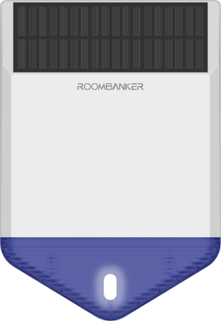 | A function that used to find your Indoor Siren among numerous devices. When you enable this function, the indicator in Indoor Siren will flash green to help you find the target device quickly. |
| Signal Strength Test | 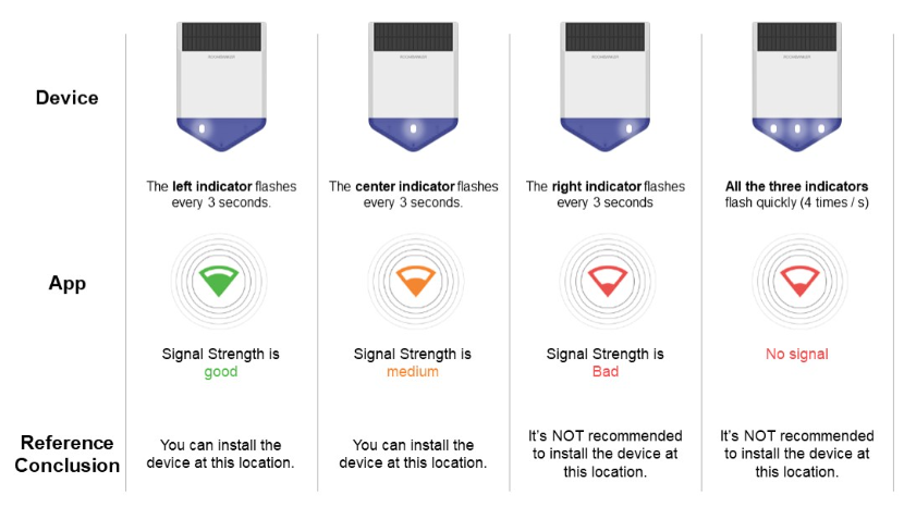 | A function that used to check the signal strength between the Indoor Siren and the hub at the tested place, which is designed to help you choose the right place for installation. When you enable this function, you can check the signal strength by watching the indicator in Indoor Siren and the feedback in app. |
| Disable Device | ON / OFF | If this button is ON, the alarm and malfunctions generated by this Indoor Siren will no longer be uploaded to the Hub and App. *It is recommended that you disable the device only if it’s defective. Before turning on this function, please ensure that you are aware of the situation to avoid possible personal injury or property damage that may result from the device not detecting and triggering an alarm. |
| Display On Homepage | ON / OFF | When enabled, the Indoor Siren will show up on homepage so that you can operate quickly. |
| User Guide | / | Click to check the user guide document of Indoor Siren. |
4.11 Keypad
*You can click Spec and QSG to check more information about Keypad.
4.11.1 Appearance
| Appearance | Description |
|---|---|
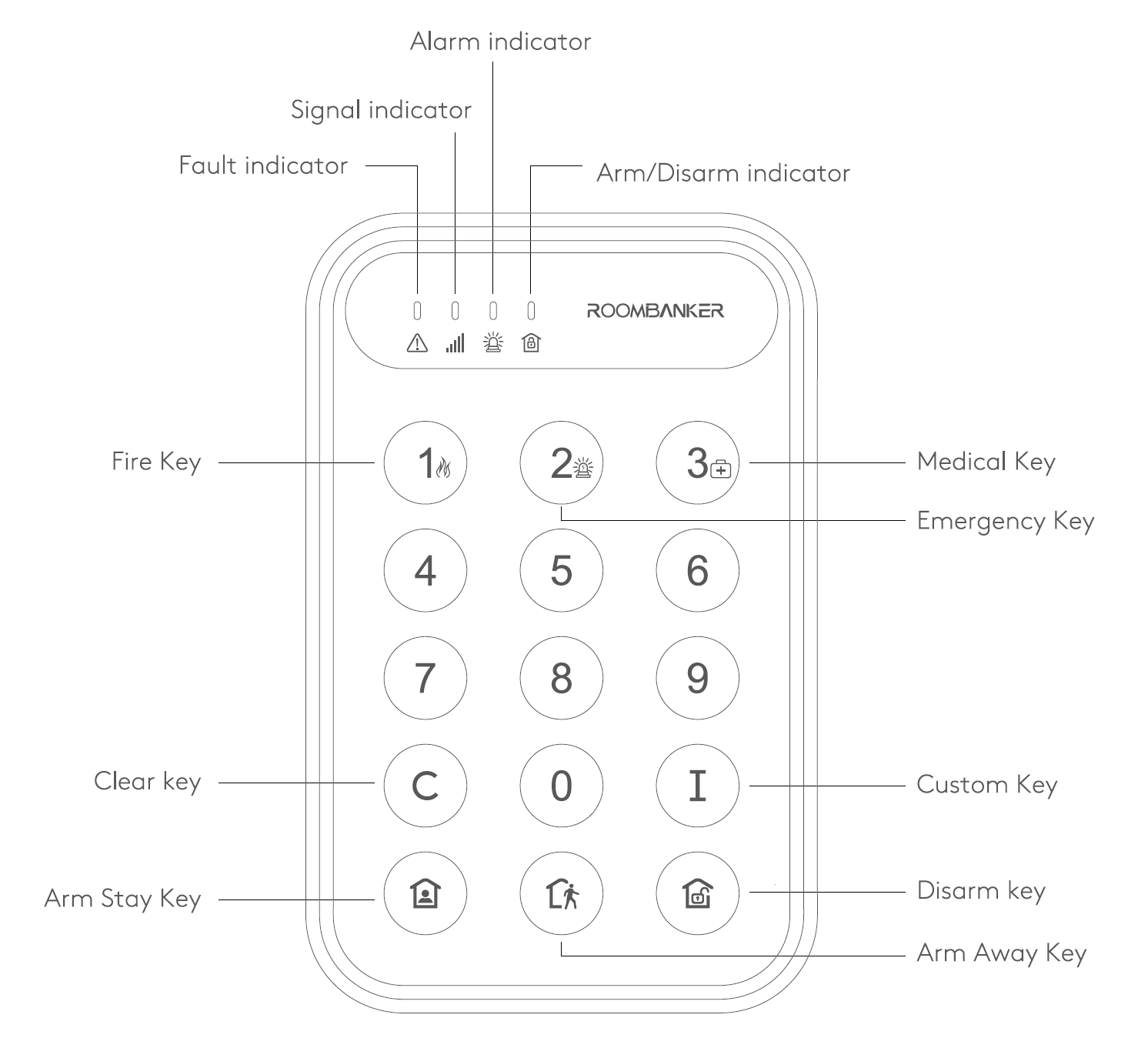
| Fault Indicator | Red, used to indicate the system fault. *The red indicator turns on when there is a fault in system. |
| Signal Indicator | Red / Orange / Green. Used to indicate the status of Signal Strength and Find Me. |
| Alarm Indicator | Red. It will flash to indicate the alarm event of system. |
| Arm/Disarm Indicator | Blue / Green. The blue indicator turns on when the system armed. |
| Numeric Key | The Numeric Keys (0 ~ 9) used for entering PIN Code for daily operations. |
| Clear Key | Clear the code you entered before and then start for a new operation. |
| Custom Key | Click to trigger the preset function you set and linked before. |
| Arm Stay Key | Arm the system in Stay Mode. |
| Arm Away Key | Arm the system in Away Mode. |
| Disarm Key | Disarm the system. *You have to enter the PIN Code to disable the system. |
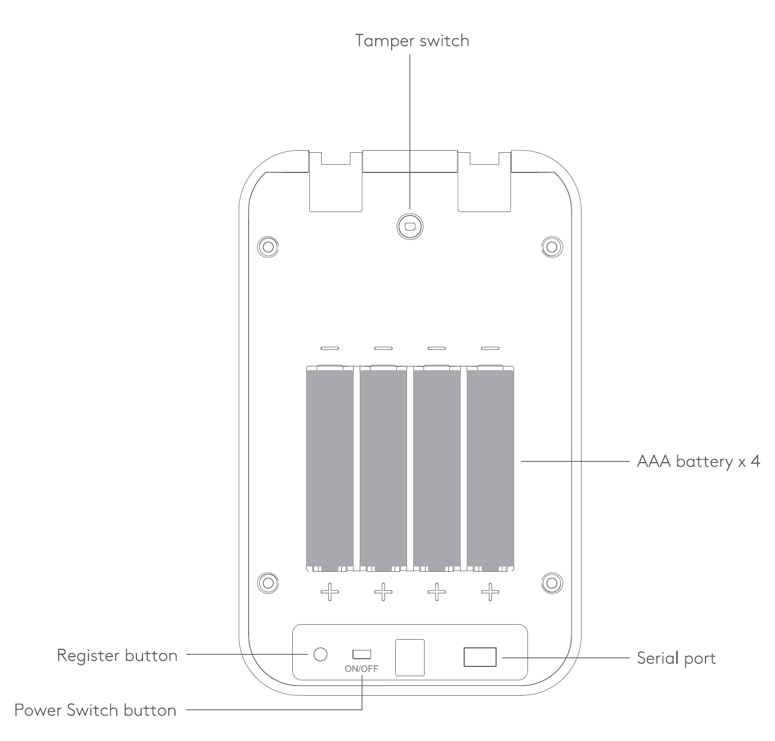
| Power Switch Button | Used to turn ON/OFF the keypad manually. |
| Register Button | Press and hold for 5s to add the Keypa to the Hub. *Register Button is only used for re-adding or connecting the keypad into another Hub. |
| Tamper Switch | Used to detect the tamper alarm status of the lid. |
4.11.2 State
| Parameter | Value | Meaning |
|---|---|---|
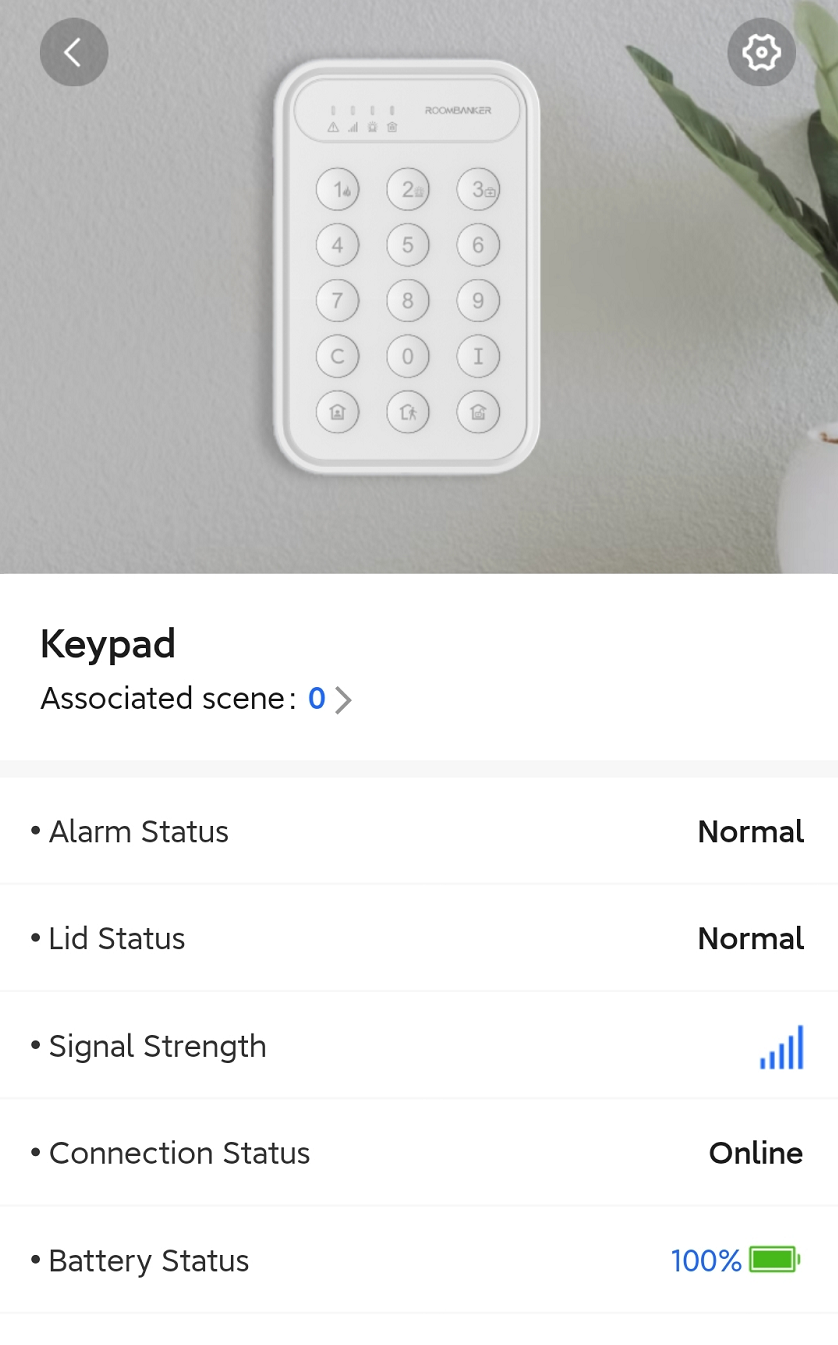
| Associated Scene | 0 ~ 64 | Shows the number of custom scenes associated with this Keypad. You can also click to view and configure the scenes. *Please turn to Charter 6. Scene Management for more details. |
| Alarm Status | Normal / Alarm | Shows if there is alarm triggered in the linked room(s). |
| Lid Status | Normal / Triggered | Shows whether the lid of Keypad is open or not. |
| Signal Strength | | Shows the signal strength between the Keypad and the Hub. |
| Connection Status | Online / Offline | Shows the connection status between the Keypad and the Hub. *The Keypad will not be functional if the status is offline. |
| Battery Status | | Shows the battery level of Keypad. *If the battery level is low, the icon will turn red and you’ll receiver a malfunction notification in App. |
4.11.3 Setting
Click "" on the top right corner and turn to “Setting”.
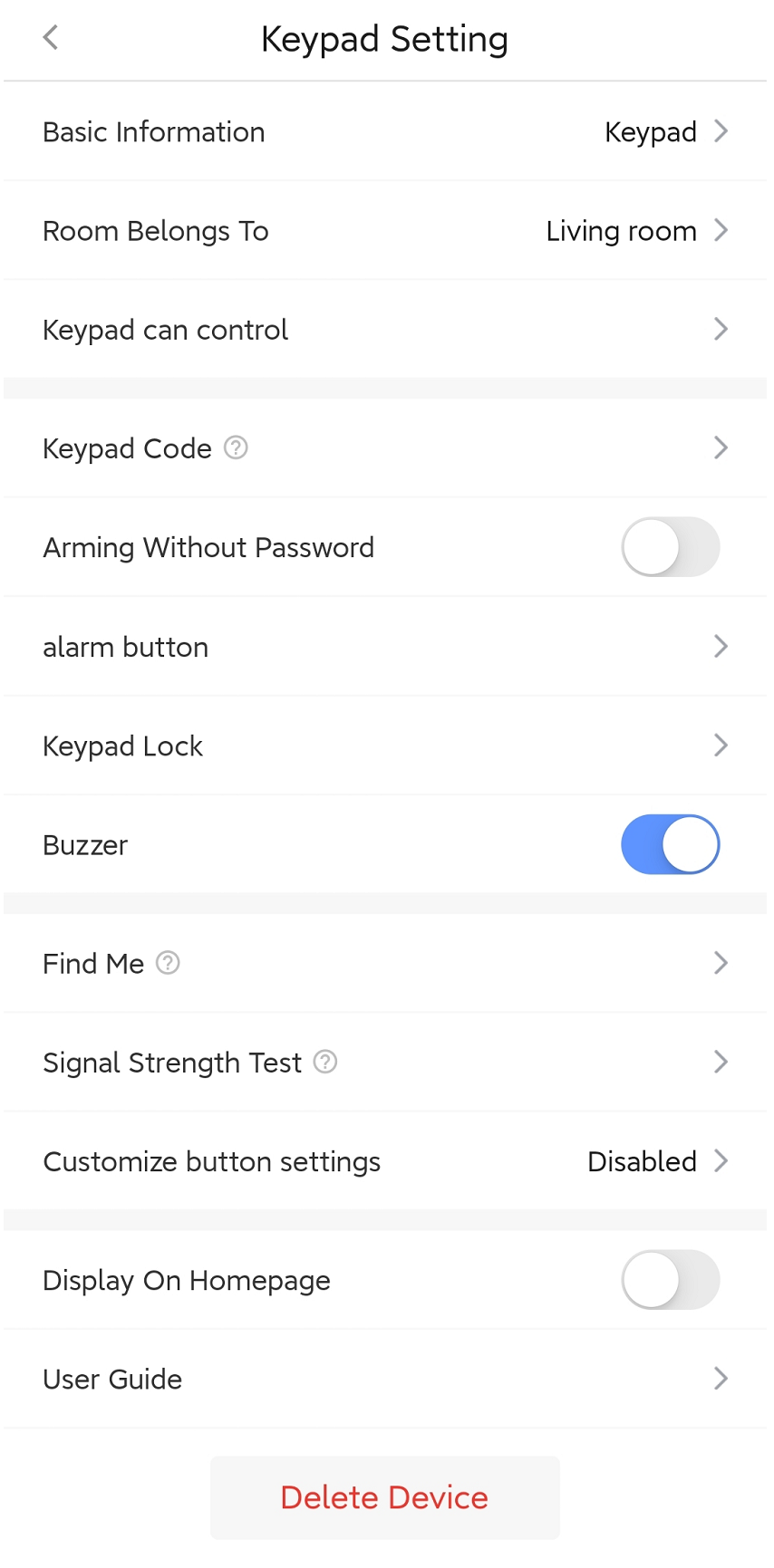
| Parameter | Value | Meaning |
|---|---|---|
| Basic Information | / | Check the basic information of this device, including MAC Address, Serial Number, etc. And you can also edit the device name here by yourself. |
| Add Room | 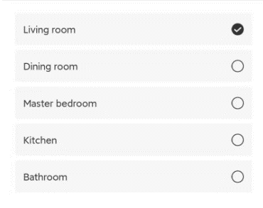 | You can select one of the rooms created before and then link the Keypad to. *When linked to a specific room, the Keypad will be displayed on the product list of the room. |
| Keypad can control | 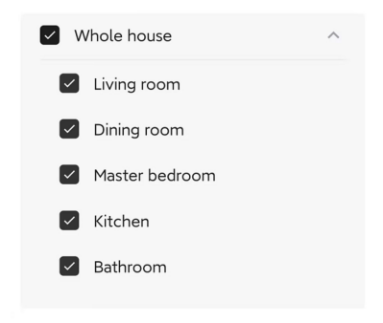 | Select one or multiple rooms that you want to control with this keypad. |
| PIN Code | 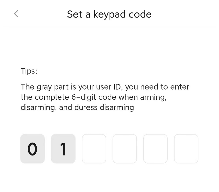 | You can set a PIN code that can be used to control the system later. *The PIN Code consists of six digits, and the first two digits are fixed ID numbers assigned by the system, while the last four digits are customized by yourself. |
| Arming Without PIN Code | ON / OFF | If this button is ON, you can just click [  ] or [ ] or [  ] in keypad to arm the system directly, without enter the PIN Code in advance. ] in keypad to arm the system directly, without enter the PIN Code in advance. |
| Alarm Button | 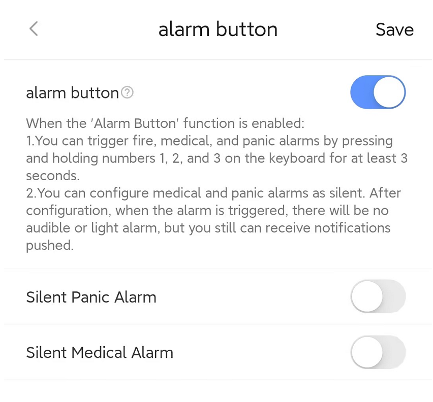 | If the button of “Alarm Button” is ON, you can trigger alarm manually by pressing and holding the special numeric keys for 3 seconds. Number Key 1 (Fire Alarm) / Number Key 2 (Panic Alarm) / Number Key 3 (Medical Alarm) You can also enable silent panic/medical alarm independently. When the button of “Silent Panic Alarm” or “Silent Medical Alarm” is ON, there will be no audible or light alarm when the alarm is triggered, but the alarm notification could still be pushed to remote terminals via app, SMS, Phone call. |
| Keypad Lock | 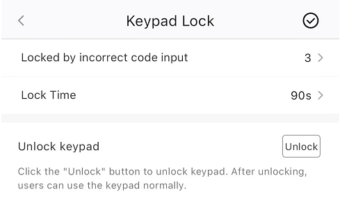 | You can set the trigger condition of keypad lock. If a keypad is locked due to multiple incorrect password attempts, Super Admin / Admin users can unlock it via the app. |
| Buzzer | ON / OFF | The buzzer is used to feedback whether your operations are performed successfully by sound, as well as alerting if any alarm triggered.You can also turn ON/OFF the buzzer of keypad here. |
| Find Me |  | A function that used to find your Keypad among numerous devices. When you enable this function, the signal indicator in Keypad will flash green to help you find the target device quickly. |
| Signal Strength Test | 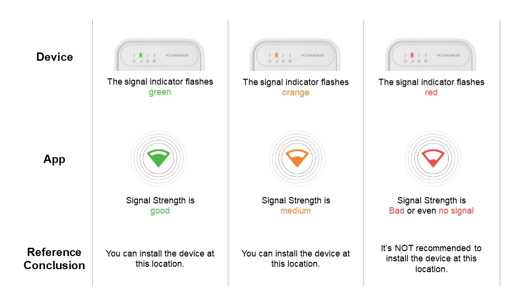 | A function that used to check the signal strength between the Keypad and the hub at the tested place, which is designed to help you choose the right place for installation. When you enable this function, you can check the signal strength by watching the signal indicator in Keypad and the feedback in app. |
| Customize Button Setting | 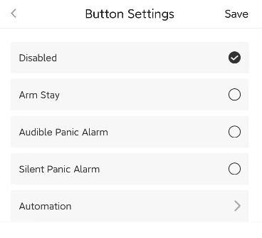 | After configured, you can press the “C” in keypad to trigger the specified event you linked with. Please make sure there is at least one custom scene configured in advance if you need to link with “Automation”. You can turn to Charter 6. Scene Management for details. |
| Display On Homepage | ON / OFF | When enabled, the Keypad will show up on homepage so that you can operate quickly. |
| User Guide | / | Click to check the user guide document of Keypad. |
| Delete Device | / | Delete the Keypad from your Hub. |
4.11.4 Operation
Arming with PIN Code
- Arm Stay:
PIN Code+ [ ] - Arm Away:
PIN Code+ [ ]
| Successful | Failed | |
|---|---|---|
| Indicator |  The Arm/Disarm Indicator lights up blue. |  The Arm/Disarm Indicator is OFF |
| Buzzer | Beeps once | Beeps three times |
Arming without PIN Code
- Press [ ] or [ ] in Keypad to arm the system directly, instead of entering the PIN Codes.
| Successful | Failed | |
|---|---|---|
| Indicator | The Arm/Disarm Indicator lights up blue. | The Arm/Disarm Indicator is OFF |
| Buzzer | Beeps once | Beeps three times |
Disarming
- Disarm the system:
PIN Code+ [ ]
]
| Successful | Failed | |
|---|---|---|
| Indicator |  The Arm/Disarm Indicator flashes green twice. | The Arm/Disarm Indicator is still blue (armed status) |
| Buzzer | Beeps once | Beeps three times |
Duress Silent Alarm
Duress Silent Alarm is designed to protect and even rescue you in critical situations, such as when faced with a burglar demanding disarming, it allows you to disarm the system as usual, and send an alarm message discreetly to the outside terminals, to ask help silently.
Duress Code = PIN Code ± 1, Only need to change the last digit of your PIN Code (±1).
e.g. Your PIN Code is "011234", you can enter "011233" or "011235" as your duress codes.
- If the last digit is "0", then you can change it to "1" or "9". *e.g. 010010 (PIN Code) → 010011 or 010019 (Duress Code).
- If the last digit is "9", then you can change it to "8" or "0". *e.g. 022009 (PIN Code) → 022000 or 022008 (Duress Code).
- Duress Disarming:
Duress Code+ [ ]
| Successful | Failed | |
|---|---|---|
| Indicator | The Arm/Disarm Indicator flashes green twice. | The Arm/Disarm Indicator is still blue (armed status) |
| Buzzer | Beeps once | Beeps three times |
Alarm Button
You can also trigger alarm manually in case of any emergency or dangerous incident, then the sirens will start to announce the alarm in different sounds within 0.5s, and the alarms will be pushed to remote terminals via app notification, SMS, Phone Call and so on.
Fire Alarm: Press and hold [
 ] for 3 seconds to trigger a fire alarm.
Panic Alarm: Press and hold [
 ] for 3 seconds to trigger a panic alarm.Note : There will be no sound or strobe alarm if the function of “Silent Panic Alarm” is ON.
Panic Alarm: Press and hold [
 ] for 3 seconds to trigger a medical alarm.Note : There will be no sound or strobe alarm if the function of “Silent Medical Alarm” is ON.
Customize Button
- Custom Function: PIN Code + [
 ]
]
| Successful | Failed | |
|---|---|---|
| Buzzer | Beeps once | Beeps three times |
4.12 Keyfob
*You can click Spec and QSG to check more information about Keyfob.
4.12.1 Appearance
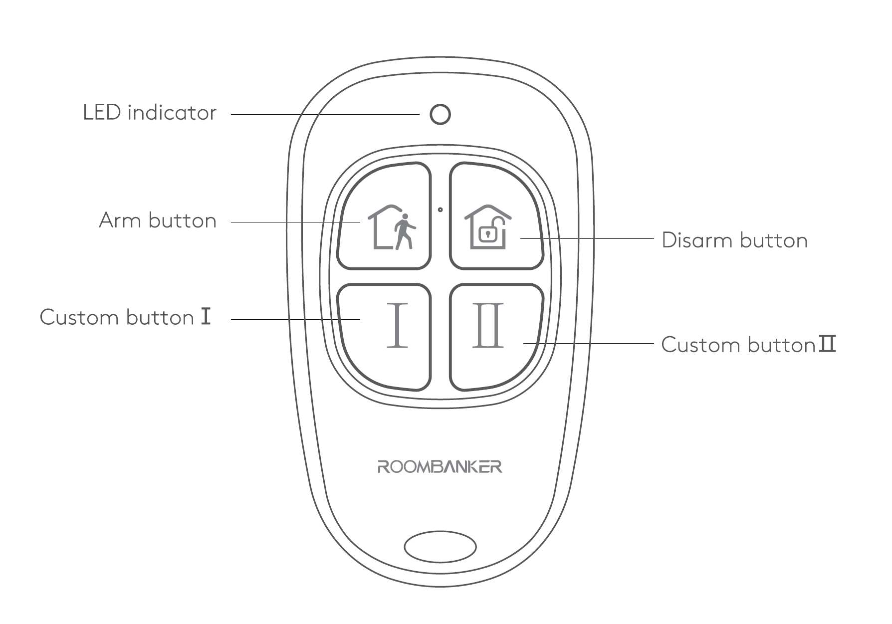
| Appearance | Description |
|---|---|
| LED Indicator | Red / Red. Used to indicate the result of your operations. |
| Arm Button | Used to arm the system in one button. |
| Disarm Button | Used to disarm the system in one button. |
| Custom Button Ⅰ / Ⅱ | Click to trigger the preset function you set and linked before. |
4.12.2 State
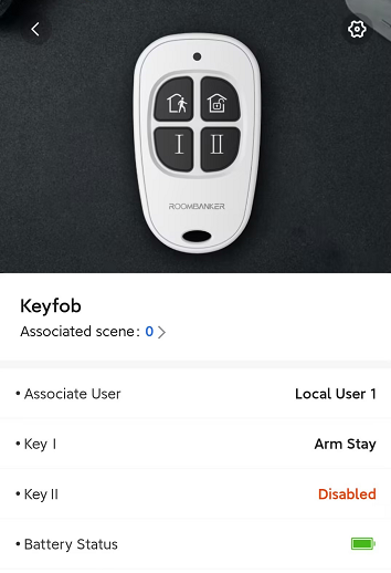
| Parameter | Value | Meaning |
|---|---|---|
| Associated Scene | 0 ~ 64 | Shows the number of custom scenes associated with this Keyfob. You can also click to view and configure the scenes. *Please turn to Charter 6. Scene Management for more details. |
| Associated User | Not associated(Default) | Shows the associated user for this keyfob. *You need to associate the keyfob with a specific user at first, so that you can use keyfob to control the system. |
| Key Ⅰ / Ⅱ | Disabled(Default) | After configured, you can press the custom button in keyfob to trigger the specified event that you linked with. Please make sure there is at least one custom scene configured in advance if you need to link with “Automation”. **Please turn to Charter 6. Scene Management for more details. |
| Battery Status | Shows the battery level of Keyfob. |
4.12.3 Setting
Click "" on the top right corner and turn to “Setting”.
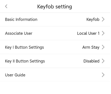
| Parameter | Value | Meaning |
|---|---|---|
| Basic Information | / | Check the basic information of this device, including MAC Address, Serial Number, etc. And you can also edit the device name here by yourself. |
| Associated User | Local User / App User (User-defined) | When the keyfob is associated with a user, the user can operate and control the system with keyfob within the scope of the permissions granted. *A keyfob is only able to be associated with one user. Please turn to Charter 5. User Management for more detail about users. |
| Key Ⅰ / Ⅱ |  | After configured, you can press the buttons in keyfob to trigger the specified event you linked with. Please make sure there is at least one custom scene configured in advance if you need to link with “Automation”. You can turn to Charter 6. Scene Management for details. |
| User Guide | / | Click to check the user guide document. |
4.12.4 Operation
Arm Away with Keydob
- Press [ ]
Disarm with Keyfob
- Press [ ]
Custom Button with Keyfob
- Press [ Ⅰ ] or [ Ⅱ ] to trigger the preset scene you configured before.
Result Feedback
| Successful | Failed | |
|---|---|---|
| Indicator | 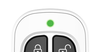 The green indicator flashes twice | 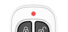 The red indicator flashes twice |
4.13 Relay
*You can click Spec and QSG to check more information about Relay.
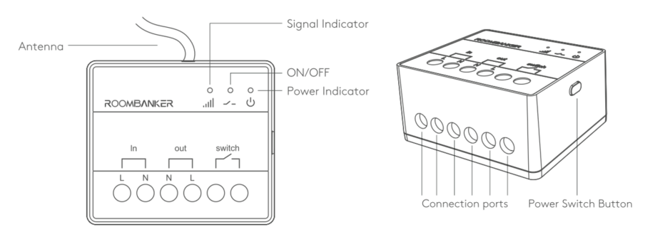
4.13.1 Appearance
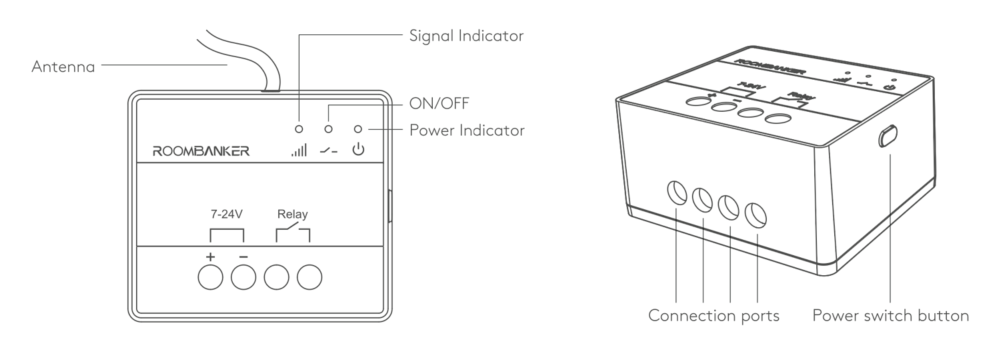
| Appearance | Description |
|---|---|
| Signal Indicator | Flashing Green / Orange / Red *Used to indicate signal strength status, Find Me status |
| Register Button | Press and hold for 5s to add the Relay to the Hub. *Register Button is only used for re-adding or connecting the peripheral to another hub |
| ON/OFF Indicator | ON: Blue indicator is on OFF: Blue indicator is off |
| Power Indicator | Used to show the power connection of relay. |
| Power Switch Button | Used to turn ON/OFF the Relay manually. |
4.13.2 State
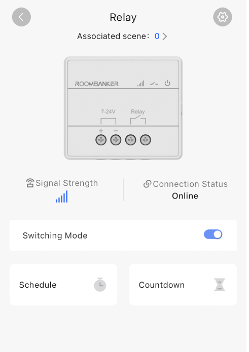
| Parameter | Value | Meaning |
|---|---|---|
| Associated Scene | 0~64 | Check how many custom scenes are associated with this Relay. You can also click to view and configure the scenes. *Please turn to Charter 6. Scene Management for more details. |
| Signal Strength | | Shows the signal strength between the Relay and the Hub. |
| Connection Status | Online / Offline | Shows the connection status between the Relay and the Hub. *The Relay will not be functional if the status is offline. |
| Relay Mode | Switching Mode / Pulse Mode | Set to either "Switch " or "Pulse " mode within the relay's device settings. |
| Schedule |  | Trigger the relay execute action when the estimated time is reached |
| Countdown |  | Trigger the relay execute action after the countdown timer expires |
4.13.3 Setting
Basic Setting
Click "" on the top right corner and turn to “Setting”.
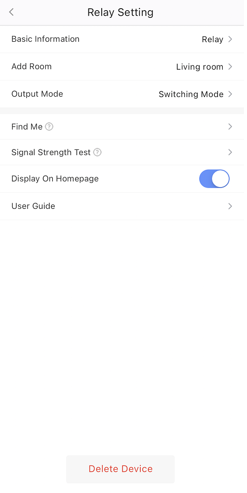
| Parameter | Value | Meaning |
|---|---|---|
| Basic Information | / | Check the basic information of this device, including MAC Address, Serial Number, etc. And you can also edit the device name here by yourself. |
| Add Room | Customized Room | You can select one of the rooms created before and then link the Relay to. *When linked to a specific room, the Relay will be displayed on the peripherals list of the room. |
| Output Mode | Switching Mode / Pulse Mode | Customize the default power-on state for both "Switch" and "Pulse" modes. For "Pulse" mode, configure the desired pulse duration. |
| Find Me | 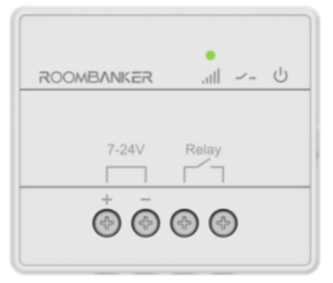 | It helps you find out your Relay when there are numerous devices. When you enable this function, the indicator in Relay will flash green to help you find the target device quickly. |
| Signal Strength Test | 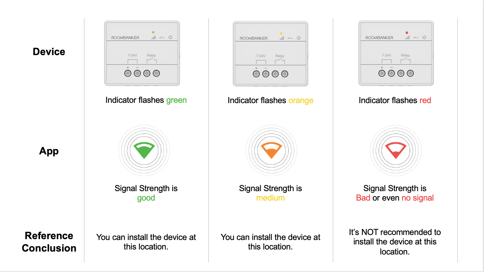 | A function that used to check the signal strength between Relay and hub at the tested place, which is designed to help you choose the right place for installation. When you enable this function, you can check the signal strength by watching the indicator in Relay and the feedback in app. |
| Display On Homepage | ON / OFF | When enabled, the Relay will show up on homepage so that you can operate quickly. |
| User Guide | / | Click to check the user guide document of Relay |
| Delete Device | / | When enabled, the Relay will show up on homepage so that you can operate quickly. |
Schedule Setting
Step 1: Click the "Schedule " and turn to the adding page.
Step 2: Click "+" on the top right corner and turn to "Schedule Configure Page"
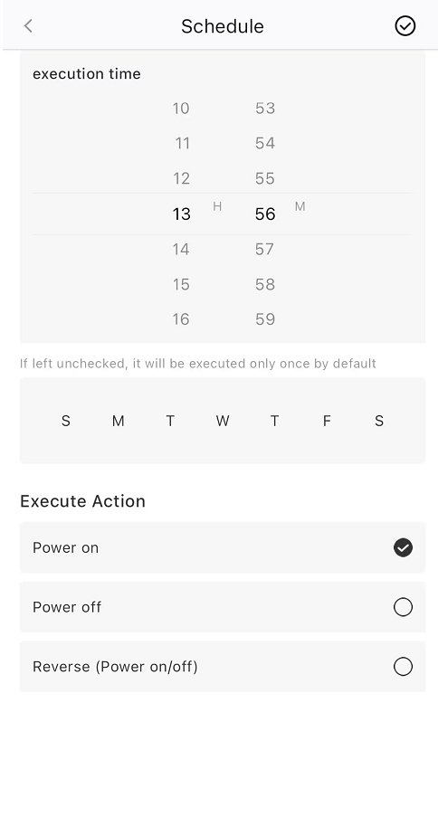
- Select the execution time and which day of the week you want to loop.
- Execute Action: The Execute Action you want the relay to perform when it reaches the time you have set.
Countdown Setting
Click "Countdown " and turn to the adding page.
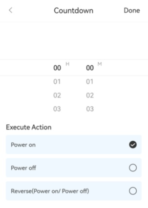
- Choose how long after you want to perform the action.
- Execute Action: The Execute Action you want to perform when it reaches the time you have set.
4.14 Wall Switch
*You can click Spec and QSG to check more information about Wall Switch.
4.14.1 Appearance
| Appearance | Description |
|---|---|
| Signal Indicator | Green / Orange / Red *Used to indicate signal strength status, and Find Me status |
| ON/OFF Indicator | ON: Blue indication is on OFF: Indicator is off |
| Power Indicator | Used to show the power status of Wall Switch |
| Power Switch Button | Used to turn ON/OFF the Wall Switch manually. |
- Only a qualified electrician or installer should install Wall Switch.
- This device is not suitable for use in locations where children are likely to be present.
4.14.2 State
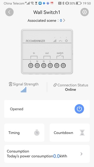
| Parameter | Value | Meaning |
|---|---|---|
| Associated Scene | 0~64 | Shows the number of custom scenes associated with this Wall Switch. You can also click to view and configure the scenes. *Please turn to Charter 6. Scene Management for more details. |
| Signal Strength | | Shows the signal strength between the Wall Switch and the Hub. |
| Connection Status | Online / Offline | Shows the connection status between the Wall Switch and the Hub. *The Wall Switch will not be functional if the status is offline. |
| Opened/Closed |  / /  | Click the button to switch the relay open/close |
| Timing | | Trigger the relay execute action when the estimated time is reached |
| Countdown | | Trigger the relay execute action after the countdown timer expires |
| Consumption | / | Show the power consumption details *Click to see more real-time information |
| Mode | Switching Mode / Pulse Mode | Set to either "Switch " or "Pulse " mode within the Wall Switch's device settings. |
4.14.3 Setting
Basic Setting
Click "" on the top right corner and turn to “Setting”.
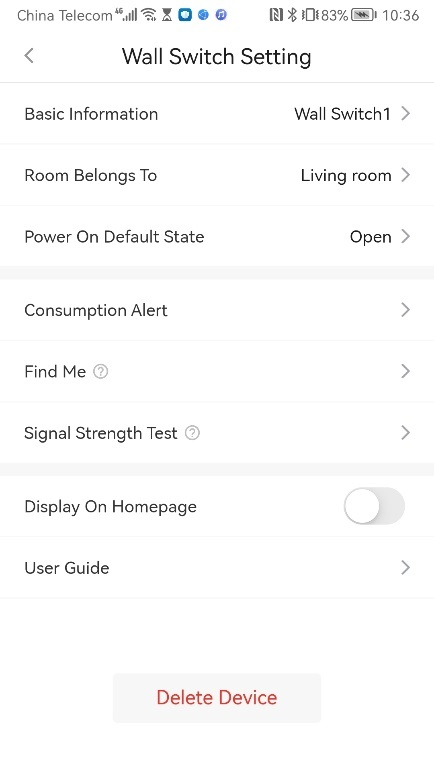
| Parameter | Setting | Meaning |
|---|---|---|
| Basic Information | / | Check the basic information of this device, including MAC Address, Serial Number, etc. And you can also edit the device name here by yourself. |
| Room belongs to | Customized Room | You can select one of the rooms created before and then link the Wall Switch to. *When linked to a specific room, the device will be displayed on the peripherals list of the room. |
| Power On Default State | ON / OFF / Last Status | You can select if you want to in default state when power is back on OFF: When power is back on,the plug is off by default ON: When power is back on,the plug is on by default Last Status: After re-powering on, the power supply remains in the state before power outage. |
| Consumption Alert | / | You can enter a daily/weekly/monthly power warning value that will alert you if it is reached or exceeded. |
| Find Me | 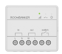 | A function that used to find your Wall Switch among numerous devices. When you enable this function, the indicator in Wall Switch will flash green to help you find the target device quickly. |
| Signal Strength Test | 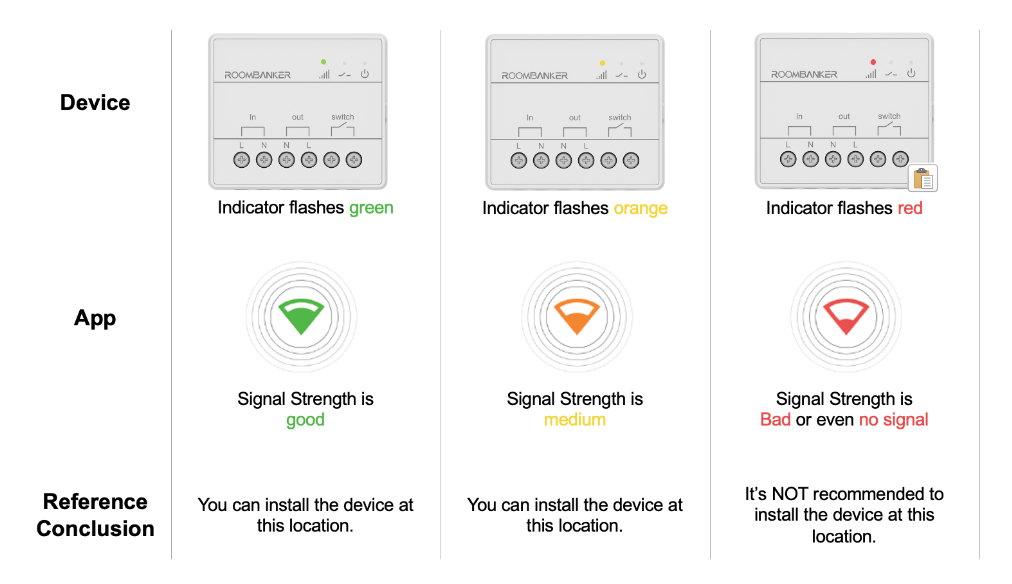 | A function that used to check the signal strength between Wall Switch and hub at the tested place, which is designed to help you choose the right place for installation. When you enable this function, you can check the signal strength by watching the indicator in Wall Switch and the feedback in app. |
| Display On Homepage | ON / OFF | When enabled, the Wall Switch will show up on homepage so that you can operate quickly. |
| User Guide | / | Click to check the user guide document of Wall Switch |
| Delete Device | / | When enabled, the Wall Switch will show up on homepage so that you can operate quickly. |
| Output Mode | Switching Mode / Pulse Mode | Customize the default power-on state for both "Switch" and "Pulse" modes. For "Pulse" mode, configure the desired pulse duration. |
Timing Setting
Step 1: Click the "Timing " and turn to the adding page.
Step 2: Click "+" on the top right corner and turn to "Timing Configure Page"
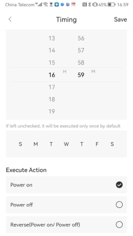
- Select the execution time and which day of the week you want to loop.
- Execute Action: The Execute Action you want the relay to perform when it reaches the time you have set.
Countdown Setting
Click "Countdown " and turn to the adding page.
- Choose how long after you want to perform the action.
- Execute Action: The Execute Action you want to perform when it reaches the time you have set.
Consumption Preview
Check the real-time power statistics, including Current power, Current and Voltage.
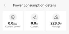
Daily, weekly, monthly and yearly trends in electricity consumption will be shown.
4.15 Smart Plug
*You can click Spec (EU / US / UK )and QSG (EU / US / UK) to check more information about Smart Plug.
4.15.1 Appearance
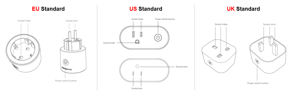
| Appearance | Description |
|---|---|
| ON/OFF Indicator | ON: Blue indicator is on OFF: Blue indicator is off |
4.15.2 State
| Parameter | Value | Meaning |
|---|---|---|
| Associated Scene | 0~64 | Shows the number of custom scenes associated with this Smart Plug. You can also click to view and configure the scenes. *Please turn to Charter 6. Scene Management for more details. |
| Signal Strength | | Shows the signal strength between the Smart Plug and the Hub. |
| Connection Status | Online / Offline | Shows the connection status between the Smart Plug and the Hub. *The Smart Plug will not be functional if the status is offline. |
| Opened/Closed | / | Click the button to switch the relay open/close |
| Timing | | Trigger the relay execute action when the estimated time is reached |
| Countdown | | Trigger the relay execute action after the countdown timer expires |
| Consumption | / | Show the power consumption details *Click to see more real-time information |
| Child lock | / | When the child lock is switched on, any key operation loses its control function,you can only control the plug through APP. *Press 4 times within 5 seconds to unlock the child lock. |
4.15.3 Setting
Basic Setting
Click "" on the top right corner and turn to “Setting”.
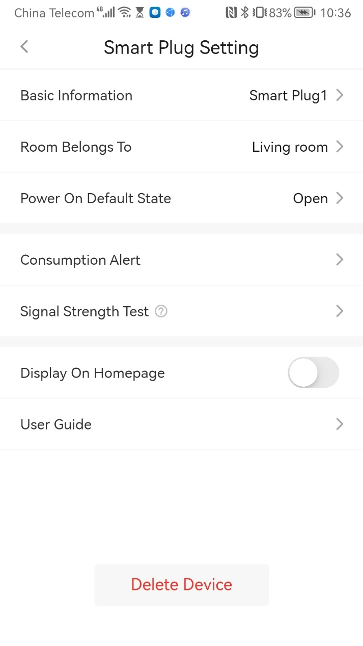
| Parameter | Setting | Meaning |
|---|---|---|
| Basic Information | / | Check the basic information of this device, including MAC Address, Serial Number, etc. And you can also edit the device name here by yourself. |
| Room belongs to | Customized Room | You can select one of the rooms created before and then link the Wall Switch to. *When linked to a specific room, the device will be displayed on the peripherals list of the room. |
| Power On Default State | ON / OFF / Last Status | You can select if you want to in default state when power is back on OFF: When power is back on, the plug is off by default ON: When power is back on, the plug is on by default Last Status: After re-powering on, the power supply remains in the state before power outage. |
| Consumption Alert | / | You can enter a daily / weekly / monthly power warning value that will alert you if it is reached or exceeded. |
| Signal Strength Test |  | A function that used to check the signal strength between the Smart Plug and the Hub at current place. When this function is enabled, you can check the feedback from the app to check the signal strength easily. |
| Display On Homepage | ON / OFF | When enabled, the Wall Switch will show up on homepage so that you can operate quickly. |
| User Guide | / | Click to check the user guide document of Wall Switch |
| Delete Device | / | When enabled, the Wall Switch will show up on homepage so that you can operate quickly. |
Timing Setting
Step 1: Click the "Timing " and turn to the adding page.
Step 2: Click "+" on the top right corner and turn to "Timing Configure Page"
- Select the execution time and which day of the week you want to loop.
- Execute Action: The Execute Action you want the relay to perform when it reaches the time you have set.
Countdown Setting
Click "Countdown " and turn to the adding page.
- Choose how long after you want to perform the action.
- Execute Action: The Execute Action you want to perform when it reaches the time you have set.
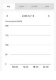
Consumption Preview
Check the real-time power statistics, including Current power, Current and Voltage.
Daily, weekly, monthly and yearly trends in electricity consumption will be shown.
4.16 Indoor IPC
*You can click Spec and QSG to check more information about Indoor IPC.
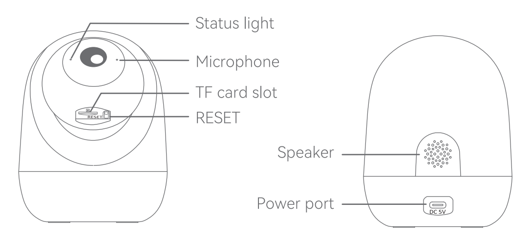
4.16.1 Appearance
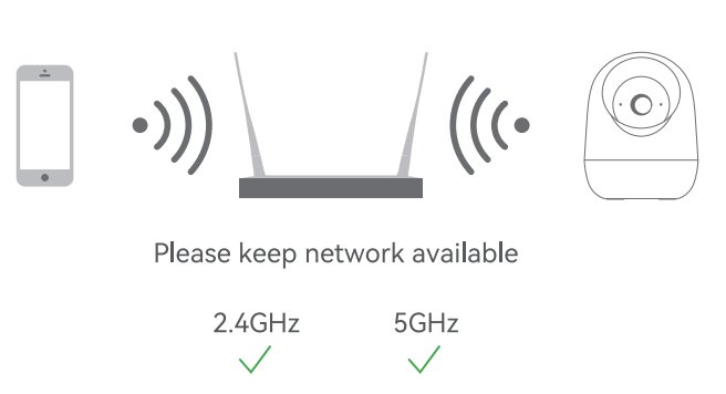
4.16.2 Set up router
The device supports the 2.4GHz &5GHz WiFi.
Ensure you have the SSID and password.
Note:
The length of the Wi-Fi SSID and password should not exceed 24 characters.
If your device has trouble connecting to the Wi-Fi network, or if you wish to switch networks, press and hold the RESET button for 5 seconds to reset the device.
4.16.3 Add Indoor Camera
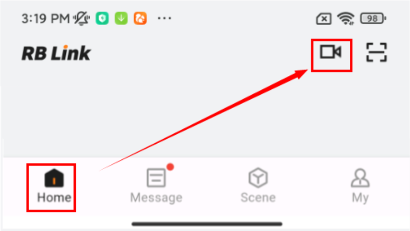
1.Plug in the cable to power up the Camera. Wait a moment until the red indicator starts flashing.
2.Click " + --> Scan " to add Camera by scanning the QR code.
3.Connect to the internet via Wi-Fi, the blue indicator turns on when the connection is successful.

4.16.4 Console
| Parameter | Setting | Meaning |
|---|---|---|
| Screenshot | / | Supports taking screenshots of the camera's shooting area, and the screenshots are stored locally on the mobile phone. |
| Lens Switch | ON / OFF | You can manually turn the lens switch, which will take effect immediately.Default is off. |
| Recording | / | Can record the current video and store it locally on the mobile phone. |
| Video Resolution | 2K / 480p / auto | Switch video resolution.Default is auto. |
| Sound | ON / OF | You can turn the camera sound on or off in the video preview page. |
| Voice Communication | / | Supports instant voice communication: Press and hold the voice button to send voice in real-time; release the button to immediately receive the other party's response. The entire process requires no waiting, making it as smooth as a face-to-face conversation. |
| Pan/Tilt | Pan: 0 ~ 350°,Tilt: 50° ~ -45° | The camera's monitoring angle can be adjusted via the up, down, left, and right buttons. |
| Sound | ON / OF | You can turn the camera sound on or off in the video preview page. |
| Select playback time | / | Supports selecting a specific time for video playback. |
| Delete playback video | / | Supports deleting specified playback videos. |
| Memory Card Capacity | / | Supports checking the TF card status, along with its total capacity and remaining capacity. |
| Playback History | ON / OF | Recording switch: ON/OFF. All-Day Recording: 24-hour recording Event Recording: Record when an event is detected. |
4.16.5 Settings
| Parameter | Value | Meaning |
|---|---|---|
| Basic Information | 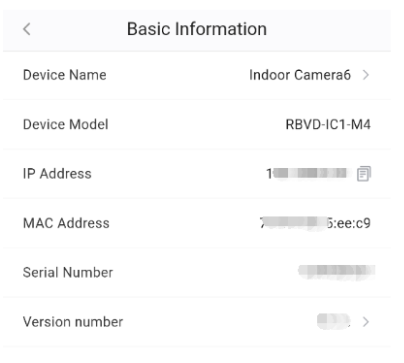 | Check the basic information of this device, including MAC Address, Serial Number, etc. And you can also edit the device name here by yourself. View device version info; upgrade if a new version is available. |
| Location | 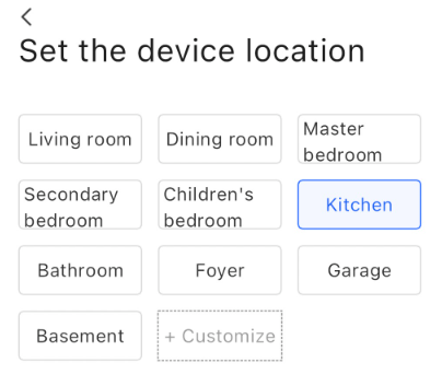 | Choose camera installation location; support custom naming. |
| User Management | 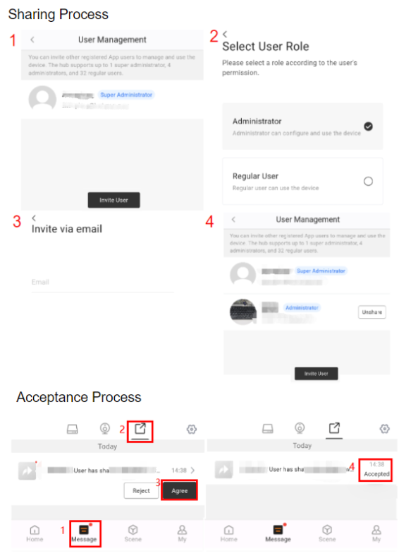 | Share Camera to APP User: Step 1: Enter "Indoor Camera Settings/User Management" on APP. Step 2: Click Invite User and select the user role from Administrator and Regular User. Step 3: Enter the Email address of the user you want to share with. Step 4: The invited user need to enter Message page, and switch to Camera Share on the top. Step 5: The invitation will be notified here, and click Agree to finish the invitation. |
| Sound | / | Supports noise detection and abnormal sound patrol, disabled by default. |
| Motion Detection | 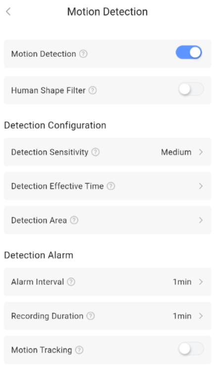 | Motion Detection: When enabled, it will detect movements in the live view in real-time and trigger the set operations. Human Shape Filter: It only reacts to the movement of people, reducing false alarms. Detection Configuration: 1.Detection Sensitivity: Sensitivity can be adjusted as needed. 2.Detection Effective Time: Supports all-day or specific time period monitoring.repeat support everyday and customize. 3.Detection Area: Customize the monitoring area, such as the door or the living room, and ignore irrelevant areas. Detection Alarm: 1.Alarm Interval: Set the alarm interval to avoid repeated alarms and storage waste.Value[30s \ 1min \ 3min \ 5min] 2.Recording Duration: The duration of the video recording triggered by movement.value[1min \ 2min \ 3min] |
| Camera Settings | 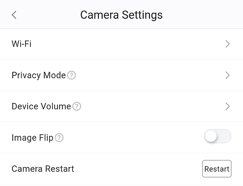 | Wi-Fi: You can switch Wi-Fi networks,connection status, signal strength, and IP address. Message Notifications: After enabling, you will receive important alerts from the camera. Motion Tracking: Automatically track the target when an abnormality is detected and continuously capture its trajector Image Flip: When the switch is turned on, the image on the camera preview page will be flipped. Privacy Mode: You can manually turn the lens switch on/off on the settings page, which will take effect immediately. You can also customize the timed tasks for turning the lens switch on/off. Device Volume: You can control the on/off status of the device speaker or adjust the volume through the switch. Scheduled Patrol: After setting up scheduled patrol, the camera will complete one full patrol cycle at the designated time. When a new scheduled patrol is added, this patrol is enabled by default.Do not set duplicate times.Up to 10 can be added. ONVIF Settings: After enabling ONVIF, display the device's SN, IP address, username, and password.Password Requirements: 4–16 characters, using only letters (a–z, A–Z) and numbers (0–9). Camera Restart: Restart the camera. |
| Storage Management | 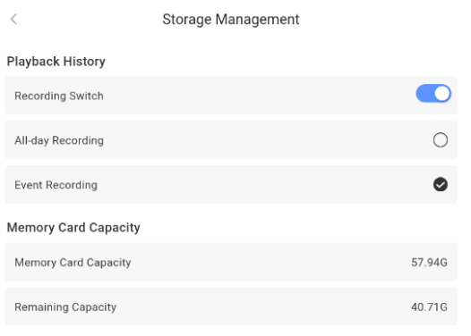 | Supports checking the TF card status, along with its total capacity and remaining capacity.On/off switch for recording. |
| User Guide | / | Click to check the user guide document of indoor IPC. |
| Delete Device | / | Delete the indoor from your hub. |
4.16.6 Key Features
- Quad View
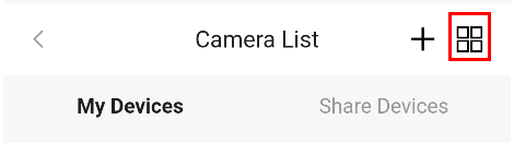
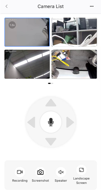
Display live feeds from up to four cameras simultaneously on a single screen.
- Digital Zoom
Smoothly zoom in and out with up to 16x magnification for enhanced detail.
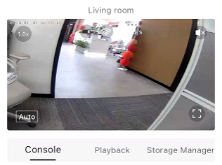
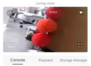
4.17 Outdoor IPC
*You can click Spec and QSG to check more information about Outdoor IPC.
4.17.1 Appearance
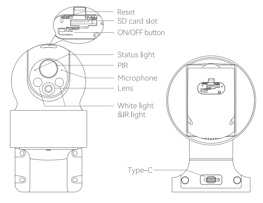
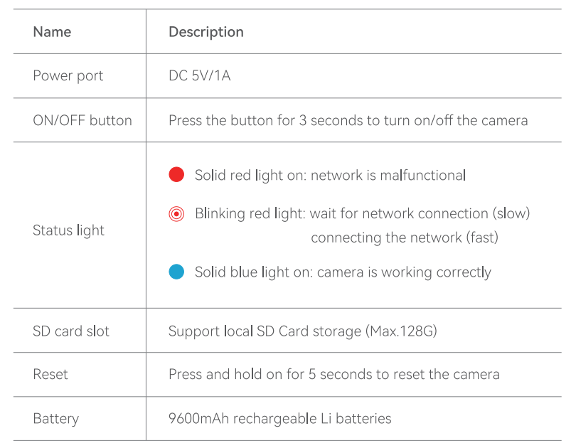
4.17.2 Set up router
The device supports 2.4GHz WiFi (does not support 5GHz).
Please set the router parameters and record your WiFi SSID and password before connecting to the WiFi network.
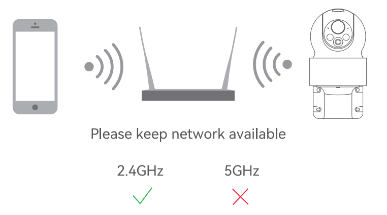
4.17.3 Add Outdoor Camera
1.Plug in the cable to power up the Camera. Wait a moment until the red indicator starts flashing.
2.Click " + --> Scan " to add Camera by scanning the QR code.
3.Connect to the internet via Wi-Fi, the blue indicator turns on when the connection is successful.
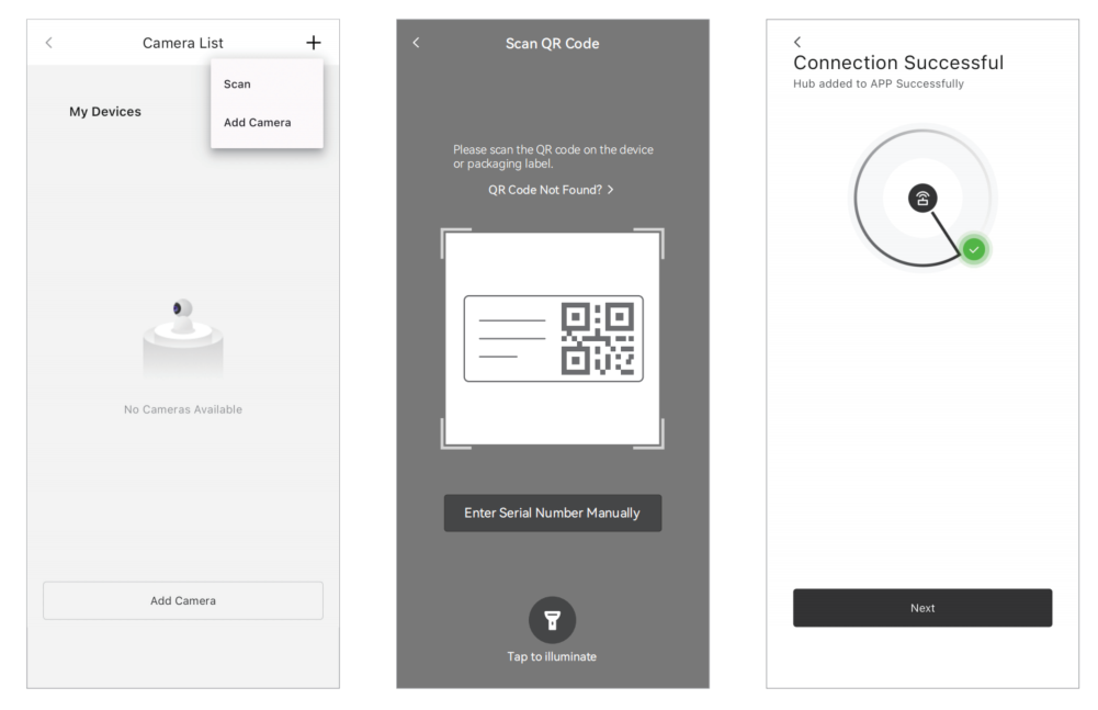
4.17.4 Console
| Parameter | Setting | Meaning |
|---|---|---|
| Screenshot | / | Supports taking screenshots of the camera's shooting area, and the screenshots are stored locally on the mobile phone. |
| Alarm | ON / OFF | The camera plays an alarm sound.Default is off. |
| Recording | / | Can record the current video and store it locally on the mobile phone. |
| Camera Light | ON / OFF | Control the on/off of the camera light.Default is off. |
| Voice Communication | / | Supports instant voice communication: Press and hold the voice button to send voice in real-time; release the button to immediately receive the other party's response. The entire process requires no waiting, making it as smooth as a face-to-face conversation. |
| Lens Rotation | Pan: 0 ~ 350°,Tilt: -90° ~ 30° | The camera's monitoring angle can be adjusted via the up, down, left, and right buttons. |
| Sound | ON / OF | You can turn the camera sound on or off in the video preview page. |
| Video Resolution | 2K / 480p / auto | Switch video resolution.Default is auto. |
| Select playback time | / | Supports selecting a specific time for video playback. |
| Delete playback video | / | Supports deleting specified playback videos. |
| Memory Card Capacity | / | Supports checking the TF card status, along with its total capacity and remaining capacity. |
| Event Recording Switch | ON / OF | On: Record when an event is detected Off: Do not record |
4.17.5 Settings
| Parameter | Value | Meaning |
|---|---|---|
| Basic Information | 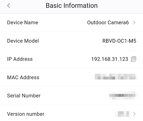 | Check the basic information of this device, including MAC Address, Serial Number, etc. And you can also edit the device name here by yourself. View device version info; upgrade if a new version is available. |
| Location | | Choose camera installation location; support custom naming. |
| User Management | | Share Camera to APP User: Step 1: Enter "Outdoor Camera Settings/User Management" on APP. Step 2: Click Invite User and select the user role from Administrator and Regular User. Step 3: Enter the Email address of the user you want to share with. Step 4: The invited user need to enter Message page, and switch to Camera Share on the top. Step 5: The invitation will be notified here, and click Agree to finish the invitation. |
| Motion Detection | 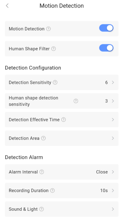 | Motion Detection: When enabled, it will detect movements in the live view in real-time and trigger the set operations. Human Shape Filter: It only reacts to the movement of people, reducing false alarms. Detection Configuration: 1.Detection Sensitivity: Sensitivity can be adjusted as needed.Larger value means more sensitivity.Value[1–10] 2.Human shape detection sensitivity: Sensitivity can be adjusted as needed.Larger value means more sensitivity.Value[1–5] 3.Detection Effective Time: Supports all-day or specific time period monitoring.repeat support everyday and customize. 4.Detection Area: Customize the monitoring area, such as the door or the living room, and ignore irrelevant areas. Detection Alarm: 1.Alarm Interval: Set the alarm interval to avoid repeated alarms and storage waste.Value[2min \ 5min \ 10min \ Close] 2.Recording Duration: The duration of the video recording triggered by movement.value[10s \ 20s \ 30s] 3.Sound & Light: You can configure the method of the acoustic-optic alarm and the acoustic-optic alarm plan. 3.1 acoustic-optic alarm: supports sound only, light only, sound and sound-light. 3.2 acoustic-optic alarm plan:Scheduled start and end times can be set, with repeat frequency configurable as required. If the set start time is earlier than the current time, the schedule runs the same day; if later, it runs the following day. |
| Camera Settings | 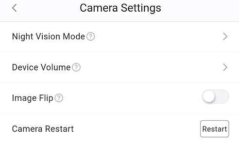 | Message Notifications: After enabling, you will receive important alerts from the camera. Night Vision Mode: You can customize the color of the image in night vision mode. Device Volume: You can control the on/off status of the device speaker or adjust the volume through the switch. Image Flip: When the switch is turned on, the image on the camera preview page will be flipped. Camera Restart: Restart the camera. |
| Storage Management | 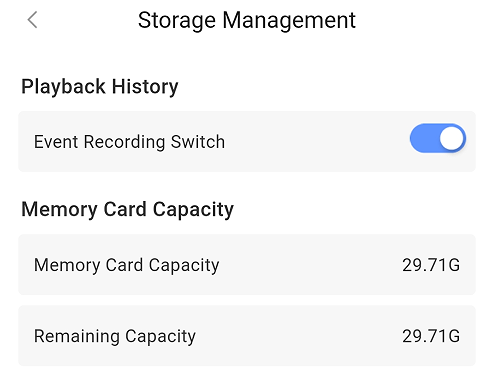 | Supports checking the TF card status, along with its total capacity and remaining capacity. On/off switch for event-detection recording. |
| User Guide | / | Click to check the user guide document of Outdoor IPC. |
| Delete Device | / | Delete the Outdoor from your hub. |
4.17.6 Key Features
- Quad View
Display live feeds from up to four cameras simultaneously on a single screen.
- Digital Zoom
Smoothly zoom in and out with up to 16x magnification for enhanced detail.
4.18 Outdoor PIR Sensor(IR+MW)
You can click Spec and QSG to check more information
4.18.1 Appearance

| Appearance | Description |
|---|---|
| Registration Mode | Green light flashes (250ms on / 750ms off) when powered on or network button held. |
| Find Me | Green light flashes (1s on / 1s off). |
| Signal Strength Detection | Auto-off after 2 min. Strong: Green (3s on / 3s off) Medium: Orange (3s on / 3s off) Weak: Red (3s on / 3s off) Lost: Red (250ms on / 250ms off) |
| Motion Detected | Red light flashes once every 500ms. |
4.18.2 State
| Parameter | Value | Meaning |
|---|---|---|
| Associated scene | 0 ~ 64 | Shows the number of custom scenes associated with this PIR. You can also click to view and configure the scenes. *Please turn to Charter 6. Scene Management for more details. |
| Arm Status | Arm / Disarm | Shows the arm status of the PIR. When it’s armed, the PIR could detect motion events and then report alarm to Hub immediately. *The PIR will enter sleep mode for energy-saving. |
| Alarm Status | Normal / Alarm | Shows whether the PIR is triggered. *Alarm will only be triggered when PIR is armed. |
| Lid Status | Normal / Triggered | Shows whether the lid of PIR is open or not. |
| Signal Strength | | Shows the signal strength between the PIR and the hub. |
| Connection Status | Online / Offline | Shows the connection status between the PIR and the Hub. *The PIR will not be functional if the status is offline. |
| Battery Status | | Shows the battery level of PIR. *If the battery level is low, the icon will turn red and you’ll receiver a malfunction notification in App. |
4.18.3 Setting
Click "" on the top right corner and turn to “Setting”.
| Parameter | Value | Meaning |
|---|---|---|
| Basic Information | / | Check the basic information of this device, including MAC Address, Serial Number, etc. And you can also edit the device name here by yourself. |
| Add Room | | You can select one of the rooms created before and then link the PIR to. *When linked to a specific room, the PIR will be displayed on the product list of the room, and the PIR could begin for detecting when the room is armed. |
| Find Me | A function that used to find your PIR among numerous devices. When you enable this function, the indicator in PIR will flash green to help you find the target device quickly. | |
| Signal Strength Test |  | A function that used to check the signal strength between PIR and hub at the tested place, which is designed to help you choose the right place for installation. When you enable this function, you can check the signal strength by watching the indicator in PIR and the feedback in app. |
| Installation Test | A function that used to test whether the PIR is installed properly. When you enable this function, you can walk in the room to test if the PIR can detect and trigger an alarm properly. The indicator will flash red when it detects successfully. | |
| Tamper detection | ON / OFF | When the tamper detection is enabled, if the tamper switch is triggered while the hub is armed, an alarm will be triggered. |
| Detection Sensitivity | High / Medium / Low | Adjust sensitivity per actual installation environment to cut false & missed alarms and boost detection accuracy. |
| Firmware Upgrade | The device supports firmware upgrade functionality and can be updated remotely over the air. The system periodically checks for version updates, allowing users to download and install firmware updates via the mobile app when the Hub is connected to the internet. | |
| Disable Device | ON / OFF | If this button is ON, the alarm and malfunctions generated by this PIR will no longer be uploaded to the Hub and App. *It is recommended that you disable the device only if it’s defective. Before turning on this function, please ensure that you are aware of the situation to avoid possible personal injury or property damage that may result from the device not detecting and triggering an alarm. |
| Display On Homepage | ON / OF | When enabled, the PIR will show up on homepage so that you can operate quickly. |
| User Guide | / | Click to check the user guide document of PIR. |
| Delete Device | / | Delete the PIR from your hub. |
| 24-hour Alarm | ON / OF | Enable the PIR Sensor to be armed 24h,it will trigger an alarm whenever activated. |
4.19 Door Window Sensor(Anti-masking)
*You can click Spec and QSG to check more information about Door Window Sensor(Anti-masking).
4.19.1 Appearance
| Appearance | Description |
|---|---|
| LED Indicator | Red / Green / Orange *Used to indicate alarm status, signal strength status, and Find Me status. |
| Register Button | Press and hold for 5s to add the Door Window Sensor to the Hub. *Register Button is only used for re-adding or connecting the peripheral to another hub. |
| Tamper Switch / Tamper Button | Used to detect the tamper alarm status of the lid. |
4.19.2 State
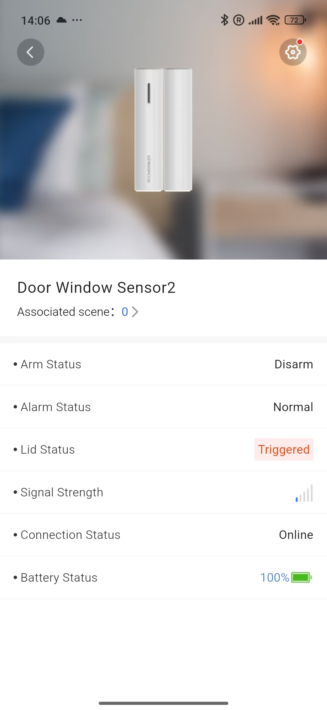
| Parameter | Value | Meaning |
|---|---|---|
| Associated scene | 0 ~ 64 | Shows the number of custom scenes associated with this Door Window Sensor. You can also click to view and configure the scenes. *Please turn to Charter 6. Scene Management for more details. |
| Arm Status | Arm / Disarm | Shows the arm status of the Door Window Sensor. When it’s armed, the Door Window Sensor could detect open/close events and then report alarm to Hub immediately. |
| Alarm Status | Normal / Alarm | Shows whether the Door Window Sensor is triggered. |
| Lid Status | Normal / Triggered | Shows whether the Door Window Sensor’s lid is opened or not. |
| Signal Strength | | Shows the signal strength between the Door Window Sensor and the Hub. |
| Connection Status | Online / Offline | Shows the connection status between the Door Window Sensor and the Hub. *The Door Window Sensor will not be functional if the status is offline. |
| Battery Status | | Shows the battery level of Door Window Sensor. *If the battery level is low, the icon will turn red and you’ll receive a malfunction notification in App. |
4.19.3 Setting
Click "" on the top right corner and turn to “Setting”.
| Parameter | Value | Meaning |
|---|---|---|
| Basic Information | / | Check the basic information of this device, including MAC Address, Serial Number, etc.And you can also edit the device name here by yourself. |
| Add Room | | You can select one of the rooms created before and then link the Door Window Sensor to. *When linked to a specific room, the Door Window Sensor will be displayed on the product list of the room, and the alarm will be triggered only when the room is armed. |
| Find Me | 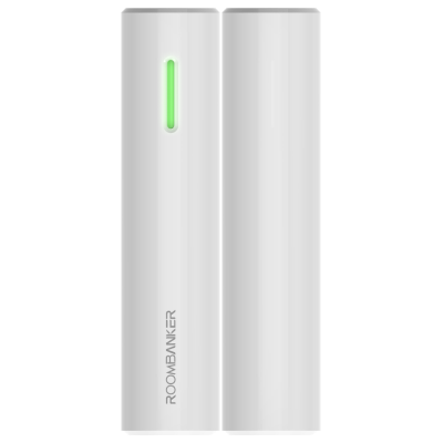 | A function that used to find your Door Window Sensor among numerous devices. When you enable this function, the indicator in Door Window Sensor will flash green to help you find the target device quickly. |
| Signal Strength Test | | A function that used to check the signal strength between Door Window Sensor and hub at the tested place, which is designed to help you choose the right place for installation. When you enable this function, you can check the signal strength by watching the indicators in Door Window Sensor and the feedback in app. |
| Anti-masking Test | / | After enabling this function, the device indicator light will flash green, indicating that the anti-magnetic interference test is in progress. |
| Firmware Upgrade | / | The device supports firmware upgrade functionality and can be updated remotely over the air. The system periodically checks for version updates, allowing users to download and install firmware updates via the mobile app when the Hub is connected to the internet. |
| Disable Device | ON / OFF | If this button is ON, the alarm and malfunctions generated by this Door Window Sensor will no longer be uploaded to the Hub and App. *It is recommended that you disable the device only if it’s defective. Before turning on this function, please ensure that you are aware of the situation to avoid possible personal injury or property damage that may result from the device not detecting and triggering an alarm. |
| Display On Homepage | ON / OFF | When enabled, the Door Window Sensor will show up on homepage so that you can operate quickly. |
| 24-hour Alarm | ON / OF | Enable the Door Window Sensor to be armed 24h,it will trigger an alarm whenever activated. |
| Anti-masking | ON / OF | Prevents malicious blocking & shielding, and stops deliberate sabotage from bypassing security. |
| User Guide | / | Click to check the user guide document of Door Window Sensor. |
| Delete Device | / | Delete the Door Window Sensor from your hub. |
4.20 Transmitter
*You can click Spec and QSG to check more information about Transmitter.
4.20.1 Appearance
| Appearance | Description |
|---|---|
| LED Indicator | Red / Green / Orange *Used to indicate alarm status, signal strength status, and Find Me status. |
| Register Button | Press and hold for 5s to add transmitter to the Hub. *Register Button is only used for re-adding or connecting the peripheral to another hub. |
| + – | 3.3 V / 30 mA power supply output for connecting a wired device. |
| PO+ PO- | Programmable output, open-collector, need external pull-up resistor. |
| ALARM | Inputs for connecting a wired device. |
| TAMP | Inputs for connecting a tamper of a wired device. |
4.20.2 State
| Parameter | Value | Meaning |
|---|---|---|
| Associated scene | 0 ~ 64 | Shows the number of custom scenes associated with this transmitter. You can also click to view and configure the scenes. *Please turn to Charter 6. Scene Management for more details. |
| Arm Status | Arm / Disarm | Shows the arm status of the Transmitter. When it’s armed, the Transmitter could detect open/close events and then report alarm to Hub immediately. |
| Alarm Status | Normal / Alarm | Shows whether the Transmitter is triggered. |
| Lid Status | Normal / Triggered | Shows whether the Transmitter’s lid is opened or not. |
| Signal Strength | | Shows the signal strength between the Transmitter and the Hub. |
| Connection Status | Online / Offline | Shows the connection status between the Transmitter and the Hub. *The Transmitter will not be functional if the status is offline. |
| Battery Status | | Shows the battery level of Transmitter. *If the battery level is low, the icon will turn red and you’ll receive a malfunction notification in App. |
4.20.3 Setting
Click "" on the top right corner and turn to “Setting”.
| Parameter | Value | Meaning |
|---|---|---|
| Basic Information | / | Check the basic information of this device, including MAC Address, Serial Number, etc.And you can also edit the device name here by yourself. |
| Add Room | | You can select one of the rooms created before and then link the Transmitter to. *When linked to a specific room, the Transmitter will be displayed on the product list of the room, and the alarm will be triggered only when the room is armed. |
| Find Me | 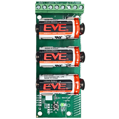 | A function that used to find your Transmitter among numerous devices. When you enable this function, the indicator in Transmitter will flash green to help you find the target device quickly. |
| Sub-Device Type | 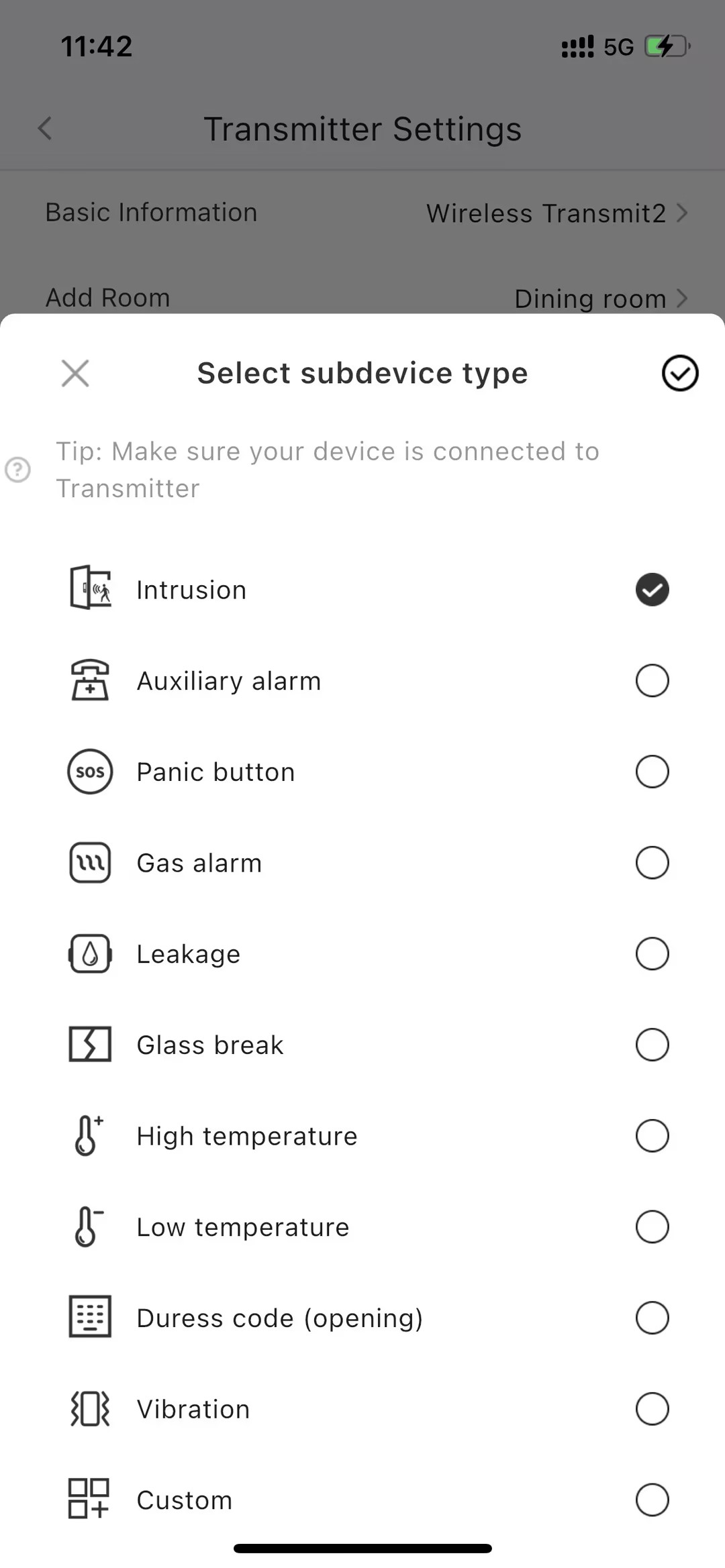 | Intrusion:Trigger an alarm on motion, door/window opening, or activation of other detectors. Fire:Generate an alarm when fire detectors are activated. Auxiliary alarm: Trigger an alarm when the auxiliary request button is pressed. Panic button:Activate an alarm upon pressing the panic button. Gas alarm:Alarm when gas concentration is exceeded. Leakage:Alarm triggered by water leakage detectors. Glass break:Alarm triggered by the glass break sensor. High temperature:Trigger an alarm when the upper temperature limit is exceeded. Low temperature:Activate an alarm when the lower temperature limit is breached. Masking:Alarm when the device masking is detected. Duress code (opening):Alarm upon entry of duress code. Vibration:Alarm when the vibration sensor is activated.This event type is only available under Pulse mode. Custom:User-configurable event type. This event is not transmitted to the security company's monitoring station. |
| External Detector Type | 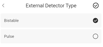 | Bistable, Pulse |
| Power Output | 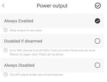 | 1. Always enabled(Keep output under any circumstances) 2.Disabled if disarmed (Cut off power output in disarmed state) 3.Always Disabled(Cut off output under any circumstances) |
| External Device Mode | 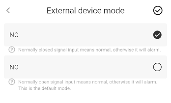 | 1.Normal Close: NC (A normally - closed signal input indicates a normal state; an alarm is triggered otherwise.) 2.Normal Open: NO (A normally - open signal input indicates a normal state; an alarm is triggered otherwise. This is the default mode.) |
| Alarm Signal Output | 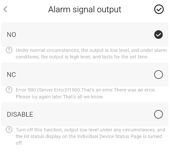 | 1.Normal Close:NC (Under normal circumstances, a low - level output is provided. In case of an alarm, a high - level output is provided for x seconds. This is the default mode.) 2.Normal Open:NO (Under normal circumstances, a high - level output is provided. In case of an alarm, a low - level output is provided for x seconds.) 3.DISABLE (Disable this function, no signal output.) Remarks: x value:0 represents continuous output, and 1 - 255s indicates the duration of continuous output. |
| Tamper Settings | 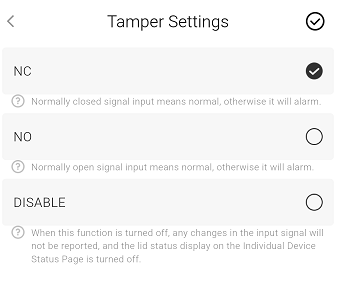 | 1.Normal Close: NC(A normally - closed signal input indicates a normal condition; an alarm is triggered otherwise. This is the default mode.) 2.Normal Open: NO(A normally - open signal input indicates a normal condition; an alarm is triggered otherwise.) 3.DISABLE: (Disable this function and do not detect signal input.) |
| Signal Strength Test | | A function that used to check the signal strength between Transmitter and hub at the tested place, which is designed to help you choose the right place for installation. When you enable this function, you can check the signal strength by watching the indicators in Transmitter and the feedback in app. |
| Firmware Upgrade | / | The device supports firmware upgrade functionality and can be updated remotely over the air. The system periodically checks for version updates, allowing users to download and install firmware updates via the mobile app when the Hub is connected to the internet. |
| Disable Device | ON / OFF | If this button is ON, the alarm and malfunctions generated by this Transmitter will no longer be uploaded to the Hub and App. *It is recommended that you disable the device only if it’s defective. Before turning on this function, please ensure that you are aware of the situation to avoid possible personal injury or property damage that may result from the device not detecting and triggering an alarm. |
| Display On Homepage | ON / OFF | When enabled, the Transmitter will show up on homepage so that you can operate quickly. |
| 24-hour Alarm | ON / OF | Enable the Transmitter to be armed 24h,it will trigger an alarm whenever activated. |
| User Guide | / | Click to check the user guide document of Transmitter. |
| Delete Device | / | Delete the Transmitter from your hub. |
4.21 Repeater
Charter 5. User Management
5.1 User Type
There are two types of user in this system, named APP User and Local User.
5.1.1 App User
Refer to the users who use APP to operate system and receive notifications, these users must be registered in RB Link APP, the APP users are classified into three types:
- Super Admin: The first user who adds the Hub in the APP.
- Admin: Can be invited by super admin from APP, and enabled as an admin.
- Regular User: Invited by super admin or admin from APP, enabled as a regular user
5.1.2 Local User
Refer to the users do not use APP, but only use keypad and keyfob to operate system.
5.2 User Authority
| User Types | APP User | Local User | ||
|---|---|---|---|---|
| Super Admin | Admin | Regular User | ||
| 1 | Up to 4 | Up to 32 | Up to 32 | |
| Add Device | √ | √ | × | × |
| Delete Device | √ | × | × | × |
| System Configuration | √ | √ | × | × |
| System Operation | √ | √ | √ | √ |
| Create/Del Room | √ | √ | × | × |
| Create/Del Scene | √ | √ | × | × |
| Operate Scene | √ | √ | √ | × |
| Message Notification | √ | √ | √ | × |
| Invite APP user (Admin) | √ | × | × | × |
| Invite APP user (Regular) | √ | √ | × | × |
| Add/Del Local User | √ | √ | × | × |
- Super Admin and Admin users are linked to all rooms by default and cannot be modified.
- Regular Users and Local Users’ room linkage can be set individually by super admin or admin, so their authorities to the system are also limited by their room authorities.
- Super admin can configure admin and regular user.
- Admin can only configure himself and regular user.
5.3 Manage Users
5.3.1 App User Management
Share Hub to APP User:
Step 1: Enter My page on APP, click Share and choose the Hub that you want to share.
Step 2: Click Invite User and select the user role from Administrator and Regular User.
Step 3: Enter the Email address of the user you want to share with.
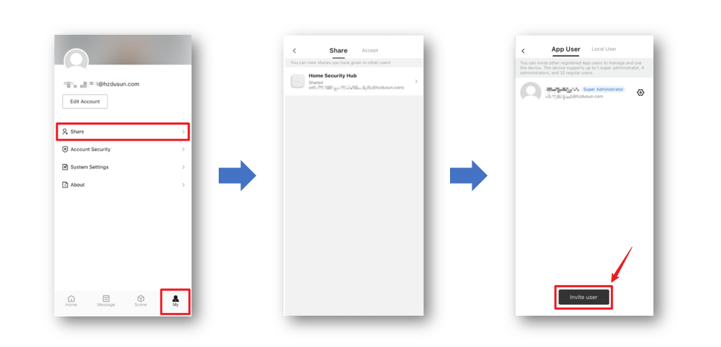
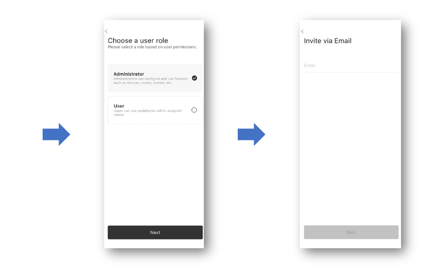
Step 4: The invited user need to enter Message page, and switch to Share on the top
Step 5: The invitation will be notified here, and click Agree to finish the invitation.
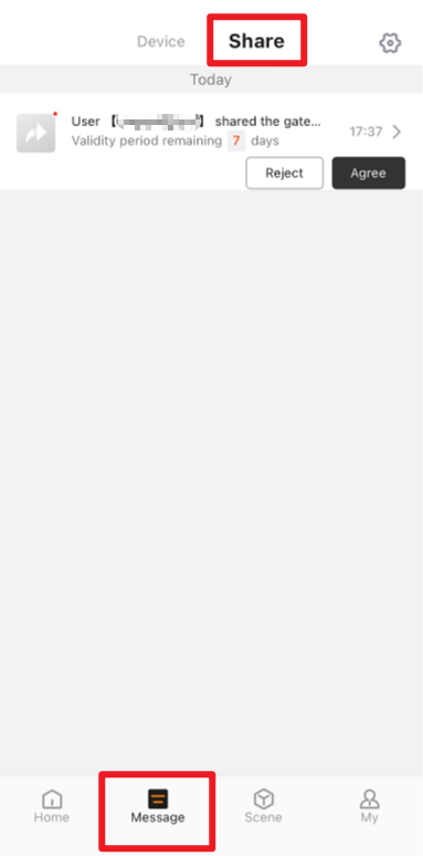
Configure App User:
- Once the sharing process has been successfully finished, enter
User Management(Hub → "Settings" → "User Management"), the new user will be shown in the list. - Click the "" button on the right side of the user to configure user authorities.
| APP User Settings Explanation | |||
|---|---|---|---|
| Notification Settings | Alarm | APP/SMS/Phone Call | To set the Hub to push notifications via APP, SMS or Phone Call if an alarm occurred. |
| Malfunction | APP/SMS/Phone Call | To set the Hub to push notifications via APP, SMS or Phone Call if a malfunction occurred. | |
| Event | APP | To set whether APP should receive event notifications. | |
| Operation | APP | To set whether APP should receive operation notifications. | |
| Add Mobile | When SMS and Phone Call are selected, the Mobile must be added as a receiver. | ||
| Keypad Code | Set a code for the user to operate keypad | ||
| Keyfob | Assign a keyfob for the user | ||
| Linked Room | Assign room permissions for the user | ||
| Delete User | |||
- The detailed definition of notification Alarm, Malfunction, Event, Operation, will be elaborated in Charter 7. Notification Management later.
- SMS and Phone Call are only supported by Home Security Hub R2 PRO, not for R2.
- For each notification, the Hub makes Phone Call and SMS to every user only once no matter successful or not.
5.3.2 Local User Management
Add a Local User
Step 1: Enter Settings page of Hub, click User Management.
Step 2: Switch to Local User on the top page.
Step 3: Click Add User and set a Nickname for the user, press Done to finish the operation.
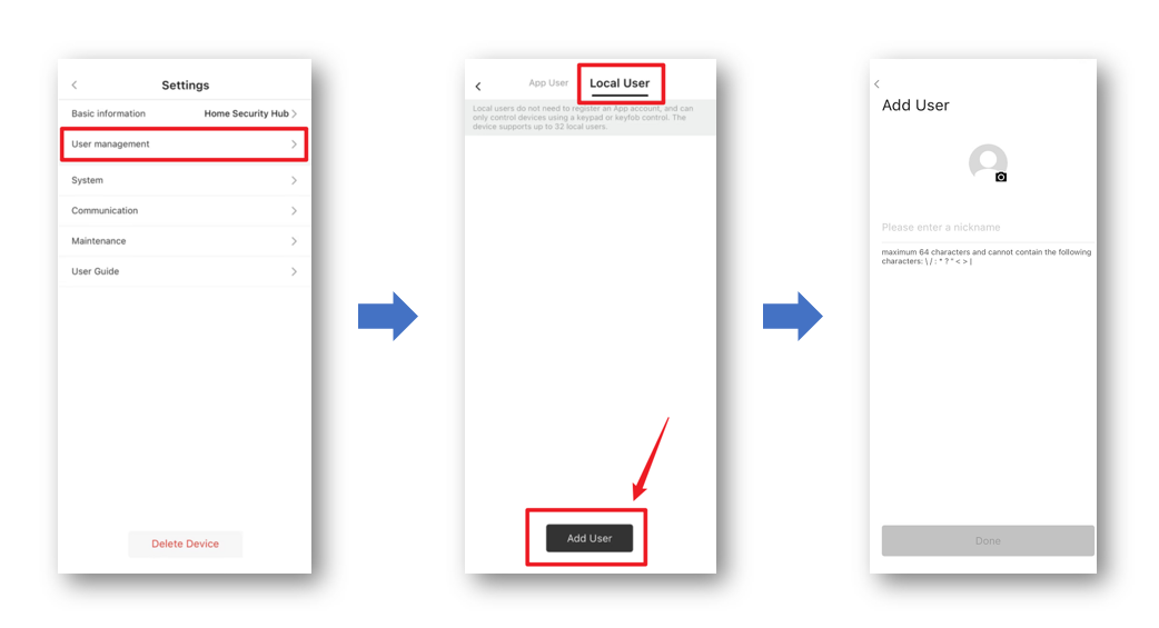
After adding successfully, click the "" button on the right side of the user to configuration.
Local User Setting Explanation
| Setting | Explanation |
|---|---|
| PIN Code | Set a code for the user to operate keypad |
| Keyfob | Assign a keyfob for the user |
| Linked Room | Assign room permissions for the user |
| User Information | Modify profile and nickname |
| Delete User | Delete user |
Charter 6. Scene Management
6.1 Security Scene
Security Scene allows you to carry out the default arming/disarming operation, as well as to create new custom arming scenes to meet daily safety needs.
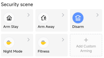
6.1.1 Default Arming / Disarming
The app supports three default modes, which are Arm Stay, Arm Away and Disarm. You can also click these buttons in Homepage.
Arm Stay
When you get home, you can press "" (Arm Stay) to let the system be armed partly. You can click ">" and then go to Arm Stay setting page and find two options can be configured:
Effective Device
Only the enabled sensors will be armed while the rest sensors keep disarmed (when you operate "
")
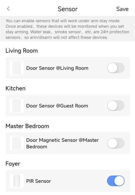
Siren ON / OFF
If you turn off the siren, when alarm is triggered, there will be no alarm sound from all the siren for the hub. The default is ON.
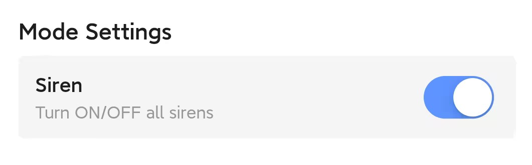
Arm Away
When you leave home, you can press "" (Arm Away) to let entire system be armed. You can also click ">" and then go to Arm Away Setting page and find two options can be configured:
Effective Device (refer to Arm Stay)
You need also notice that all the intrusion sensors will be enabled for Arm Away and you are not allowed to disable them.
Delay Setting
- Entry Delay: When you reture home, the system will delay to alarm in a certain time when sensor triggered, to allow you disarm system timely.
- Exit Delay: When you leave home, the system will be delayed to arm in a certain time after you press Arm away, to allow you leave home timely.
- Delay Rule Description
- Delay Time Range: Configurable from 10 seconds to 300 seconds, or Close
- Overall Delay Settings: All sensors under the arming mode use the same delay time, as defined in the main setting.
- Independent Delay:
- Available only in Away Arming mode.
- When Independent Delay is enabled, all sensors default to having delay disabled.
- You must then go to "Away Arming Setting → Effective Device → Sensor" configure the delay time Independent for each sensor.
- Both Away Arming and Custom Arming support delay settings. The effective delay time for a sensor is determined by the most recent configuration applied. Prerequisite for the example: PIR1 is included in both Away Arming and Custom Arming scenes.
| Scenario | Step 1 | Step 2 | Result |
|---|---|---|---|
| Scenario1 | Set Entry Delay to 10s in Custom Arming. | In Away Arming, select Independent Delay and set PIR1 delay to 20s. | PIR1 delay is 20s . |
| Scenario2 | In Away Arming, select Independent Delay and set PIR1 delay to 10s. | Set Entry Delay to 30s in Custom Arming. | PIR1 delay is 30s . |
Disarm
When you are at home and want all intrusion sensor disarmed, you can press ""(Disarm) button. In Disarm setting page, you can view which sensors will be effective when you press Disarm.
After disarming, all the alarm icon will be gone and siren sound will be stopped.
6.1.2 Custom Arming
In addition to the default armings and disarming, you can also add up to eight Custom Arming Scenes.
For example, you can configure a Night Mode to make entrance and your yard monitored but bedroom not armed. After configuration, you can just one click in Homepage or Scene page to enable Night Mode.
You can press Add Custom Arming or go to Custom Arming setting page and find these options:
1. Effective Device. Please refer to Arm Stay. (refer to Effective Device)
2. Delay Setting. Please refer to Arm Away. (refer to Delay Setting)
3. Siren. Please refer to Arm Stay. (refer to Siren ON/OFF)
4. Homepage Display. When enabled, the scene will be shown in Homepage, so that you can press the button easily.
Rule Description:
1.Custom Arming modes cannot share sensors with each other, but they may share sensors with the "Arm Stay" or "Arm Away" modes.
2.Multiple custom arming can be armed simultaneously.tap to arm, and tap again to disarm.
3.The "Disarm" button on the APP home screen disarms all zones.
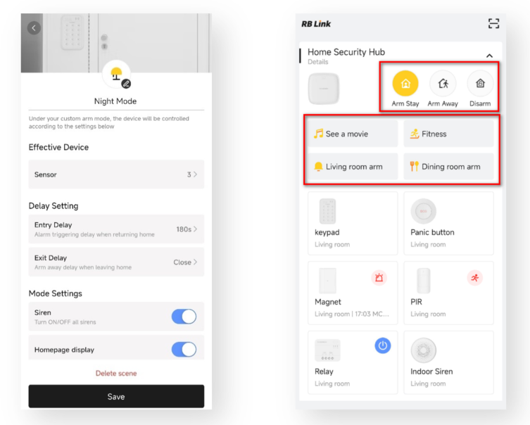
6.2 Custom Scene
There are two types of custom scenes:
Manual Click
When you create a Manual Click scene, it will shown on Scene page and you can press the scene to trigger it.
Automatic Triggering
When you create a Automatic Triggering scene, it will shown on Scene page. If the condition is triggered, an task will be executed automatically.
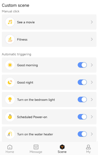
6.2.1 Create a Custom Scene
You can create up to 64 Custom Scenes for one Hub.
- Turn to "
 " (Scene) page and then press "+" to add a custom scene.
 - Click "
 " to select an icon you prefer and set a scene name.
6.2.2 Add a Trigger Condition
There are 3 types of trigger condition:
Manual Click
Manual Click allows your to enable one scene with just one click. For instance, though several steps scene configration, you can press the Manual Click scene button to switch on lights in your different rooms (via our Relay).
Note: If you choose Manual Click, you can not select any other condition.Scheduled Execution
You can select the execution time (Day / Hour / Minute).
For example, you can set a condition to power on a Smart Plug (connected with an appliance) every day at 7:00 AM.
Smart Device
The condition can be a device status change. Please refer to the following table to check supported devices as condition.
Device Type Supported Trigger Condition Smoke Detector ● Smoke alarm triggered
● Smoke alarm restoredDoor Window Sensor ● Door opened
● Door closedPIR Sensor ● PIR Sensor triggered
● PIR Sensor restoredPanic Button ● Panic Button pressed Water Leak Detector ● Water Leak detected
● Water Leak restoredTemperature & Humidity Monitor ● Temperature ≤
● Temperature ≥
● Humidity ≤
● Humidity ≥
● xx ≤ Temperature ≤ xx ℃/℉
● xx ≤ Humidity ≤ xxKeypad ● Fire alarm
● Medical alarm
● Panic alarm
Note:
- Up to 8 trigger conditions can be added when you choose Scheduled Execution and Smart Devices for one scene.
- You can select the condition rule "When any condition is met" or "when all conditions are met" if there are multi trigger conditions added.
6.2.3 Add an Execution Task
There are 3 types of execution task:
Smart Device:
The task can be a device status changes. Please refer to the following table to check supported devices as condition.
Device Type Supported Trigger Condition Relay ● Power on
● Power off
● Reverse(Power on/ Power off)Wall Switch ● Power on
● Power off
● Reverse(Power on/ Power off)Smart Plug ● Power on
● Power off
● Reverse(Power on/ Power off)Indoor / Outdoor Siren ● Sound
● Light
● Sound & LightIf you choose Smart Devices as one of the conditions, you can also configure the Effective Time Period.
- All day or Specified Time Period. If you choose Specified Time Period, you can set Start Time and End Time. The End Time can be the next day.
- You can set the scene to be executed everyday, or a specific day as you need.
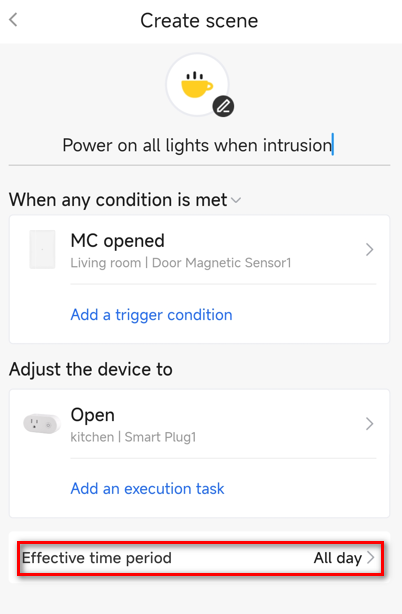
Arm:
- If you choose Manual Click or Scheduled Execution as one of trigger conditions, the task of Arm will be available to select.
- The following arming type can be selected: Arm Stay, Arm Away, and Custom Arming scene you have configured before.
For example, you can set 8:00 AM as trigger condition and Arm Away as execution task. In this case, even you forget to arm the system when you leave home, the system will arm by itself automatically.
Deferred Execution:
You can set a action delay before another Smart Device or Arm task.
If you insert a Deferred Execution (e.g. one minute) between two tasks, when a task is executed, another task will be executed one minute later.
- Deferred Execution cannot be the last task in one scene.
- Maximum 59 minutes and 59 seconds can be set.
Charter 7. Notification Management
7.1 Notification Type
In Message page, the received messages are classified into Device and Share in general, on the top of the page, by clicking to switch the contents.
7.1.1 Device
It means the notifications are generated if status changed in system devices. It has 5 types, which are listed in below form, each type has an icon design to distinguish.
| Notification Types | Icon | Definition |
|---|---|---|
| Alarm | | All the alarm notifications in system, such as Intrusion alarm, Panic alarm, Fire alarm, and more |
| Malfunction |  | All the system fault notifications, such as Low battery, External power failure, Cellular lost, and more |
| Malfunction Restored |  | All the system faults recovered to normal status |
| Event |  | Regular notifications, such as Hub is online / offline / updating, Scene auto-triggered, and more |
| Operation |  | System operation, such as Arm/Disarm, Scene manually-triggered, Automation device manually-triggered, Peripherals enable/disable |
7.1.2 Share
It means the notifications are generated by user invitation process. Only when someone is sharing Hub to you, notifications will be received and agreed there.
7.2 Notification Setting
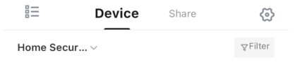
- : Enable / Disable whether to receive notifications from App;
 : Quickly select the notifications you prefer to view;
 : Set notifications as
 All ReadorClear.
Charter 8. Installation Instruction
8.1 Hub Installation
8.1.1 Noise Level
Ensuring the presence of acceptable wireless noise levels, you can check the data in app settings page. Path: Details of the Hub → > → Wireless Noise Level.
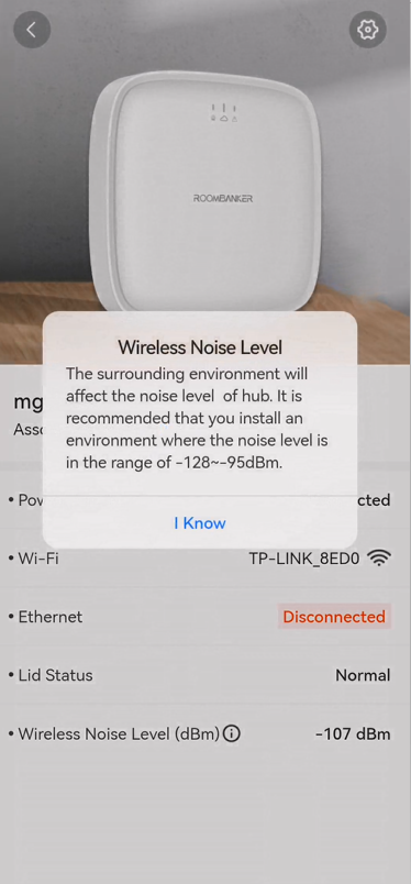
8.1.2 Considerations
DO NOT place the hub:
- Outside the premises (outdoors).
- Nearby or inside any metal objects or mirrors causing attenuation and screening of the signal.
- In places with high radio interference level.
- Close to radio interference sources: less than 1 meter from the router and power cables.
- Inside any premises with the temperature and humidity beyond the range of permissible limits. The recommended temperature is -10~45 Celsius, humidity between 30%~70%.
8.2 Peripheral Installation
- Check the detector’s installation position (indoor/outdoor)
- Check the battery. Please navagate to device's status to check the battery level in app, you will receive a message when battery is low.
- Check the LED indicator. The Hub's "Fault Indicator" will turn on when the detector's battery level is low.
- Double check the Signal Strength.
For detailed information, please check the User Guide or please visit the link blow: [Roombanker YouTube Channel](https://www.youtube.com/@Roombanker)
Charter 9. Maintenance
9.1 Battery Replacement
Identify the Battery Type:
Determine the type of battery your device uses (e.g, alkaline) and ensure you have a replacement battery of the same type.
Locate the Battery Compartment:
Find the battery compartment on your device. In many cases, it's on the back or underside of the device. Make sure you have turned off the device if needed.
Remove the Old Battery:
Follow the manufacturer's instructions to safely remove the old battery. This may involve sliding a latch, unscrewing a cover, or using a tool.
Dispose of Old Battery Properly:
If the old battery is rechargeable or contains hazardous materials, dispose of it according to local regulations. Many communities have specific battery recycling programs.
Check Battery Orientation:
Pay attention to the correct orientation of the battery. There are usually markings or diagrams in the battery compartment indicating the proper placement.
Insert the New Battery:
Carefully insert the new battery into the compartment, ensuring it is correctly oriented.
Secure the Battery Compartment:
Close or secure the battery compartment according to the device's design. Follow any locking or sealing mechanisms specified by the manufacturer.
Power On and Test:
Turn on the device and check that it operates correctly with the new battery.
Charge if Necessary:
If the battery is rechargeable, ensure it is fully charged before using the device.